Introduction
There is a bit of an evolving theme with projects on this site: design classics from the 1980’s and 90’s that may be famous in one way or another. My latest project certainly falls into this category.
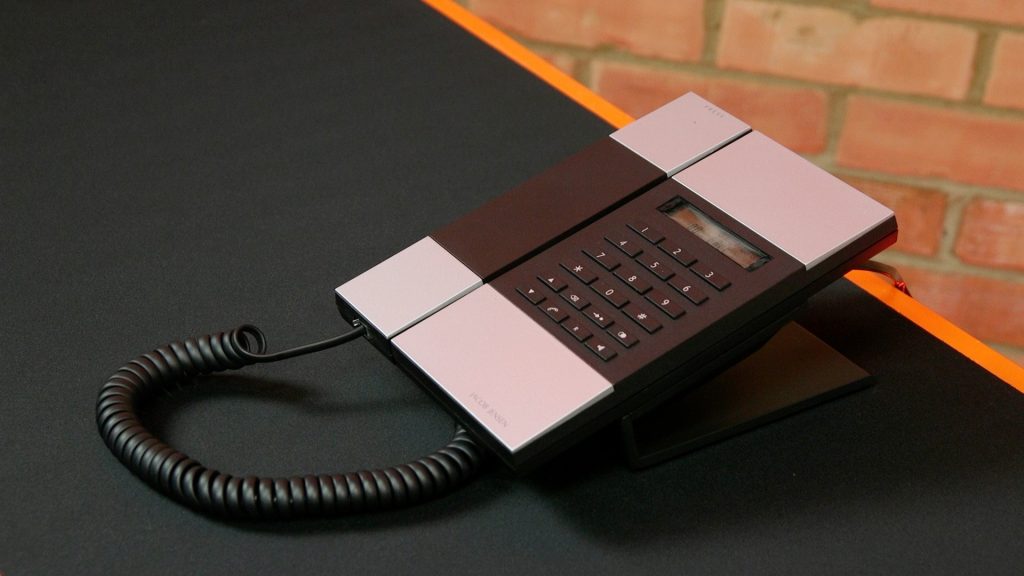
Most famous for being the telephone used by Lord Sugar in the BBC’s “The Apprentice” television programme, the Jacob Jensen Telephone 3 (T3) also happens to have sat in my mum’s living room since the middle of the 1990’s. She won it in a competition.
It is a “designer” telephone. I suppose this means:
- It looks great
- It was expensive
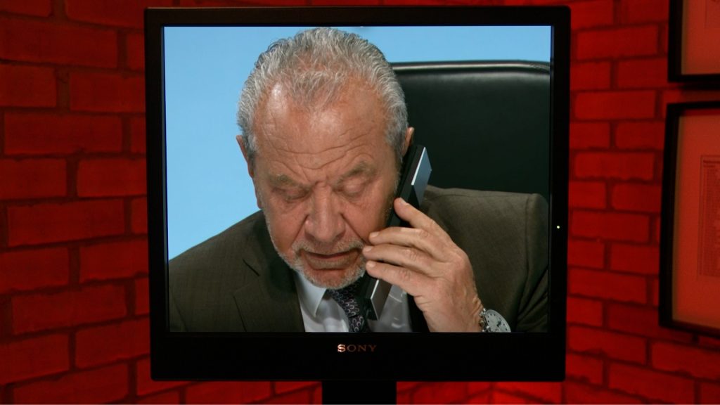
Certainly it would have been chosen by the programme makers for The Apprentice based on its good looks. When The Apprentice first aired in 2005, the used an Amstrad “Emailer” device. In the programme, Lord Sugar uses it to call through to the reception area to call the candidates through for a roasting. Nothing like a bit of product placement on the BBC for his own products! However, in 2007 Amstrad was sold to Sky (Amstrad were makers of the firm’s satellite receivers). In 2008 the Emailer was replaced with a couple of models from the Jacob Jensen design house. In the boardroom Lord Sugar took receipt of a slimline Telephone 1 (T1). In reception, they installed a Telephone 3 (T3). From series 9, they used a T3 in both locations. They are still in use to this day (series 15, 2020).
Jacob Jensen is a Danish designer famous for his minimalist style and his work for Bang and Olufsen. Many of these products can be seen in design museums around the world, such as the MOMA in New York.
The faulty phone – broadband destroyer?
Recently my parents had issues with their broadband speed. It dropped from 50Mbs to about 10Mbs. They called BT who promptly sent out an engineer. He condemned the entire telephone installation (5 phone sockets, star wiring, junction box in the garage). He disconnected everything, except one phone socket in an upstairs bedroom, to which he fitted a new-style Master Socket with in-built ADSL filter.
Although this resolved the issue with the broadband speed, it was rather unsatisfactory as the three other phones in their house no longer worked. I called BT to query this, but got short shrift. They simply suggested they could come out and, at cost, wire up some new telephone sockets.
I understand that house wiring is a likely cause of poor broadband speed. I also understand that a good solution would be to use DECT phones connected to a basestation on the Master Socket. However, there is an expense to this, and it would also mean disposing of any functioning telephones, “designer” or otherwise.
I went to take a look. I connected the telephone points back up and remade connections using a proper IDC “punch-down” tool. Our telephone lines all go back to a number of Krone blocks in the garage. I think the BT engineer had some issue with this, which is daft as Krone blocks are commonplace in telephone exchanges and street cabinets. The difference is that the wiring now hangs off the Master Socket’s user extension connection point. The “star” in the system is therefore now downstream of the Master Socket. I inspected all the devices in the house. It was obvious there was a problem with the Jacob Jensen telephone as there was a terrible crackle when it was picked up. So I took it away to see if I could fix it up.
The broadband speed has stayed at the usual 50Mbs since my intervention.
Faults
As well as the crackle when the receiver is picked up, there are a number of other issues:
- loose connector at the rear of the phone
- hum on the line. This can be heard by both parties. Mains hum, like putting an un-balanced microphone near some electrically noisy equipment.
- ringer doesn’t work
I tackled each of these faults in turn.
Hum on the line
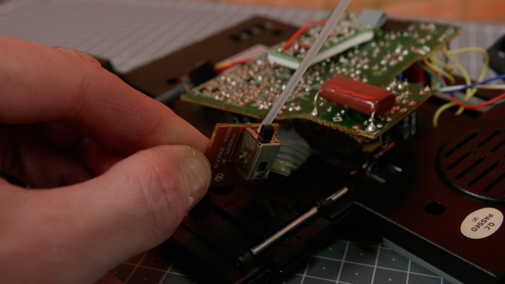
I noticed this would go away if I pressed the mute button on the handset. I therefore dismantled the handset to start with.
This required use of my new “spludger” a special thin, strong and bendy tool used to prise plastic cases from equipment, or to run around the edges of plastic to find that hidden catch.
Inside there was little to see:
- small electret (condenser) microphone
- small loudspeaker
- small PCB with a switch to intercept the microphone (the MUTE button)
- some steel weights
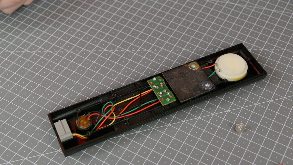
I unscrewed all the pieces for a thorough visual inspection. I found one of the mic wires was trapped under a metal weight. As I couldn’t see anything else amiss, I plugged it back in and sure enough, the fault had gone. Some times you get lucky taking things apart and just putting them back together again! Of course, this often involves “reseating” connections which can remove debris and oxidation on contacts. As the mute button just intercepted the microphone, it is hard to say which part of the circuit was at fault.
Main Telephone disassembly and crackle
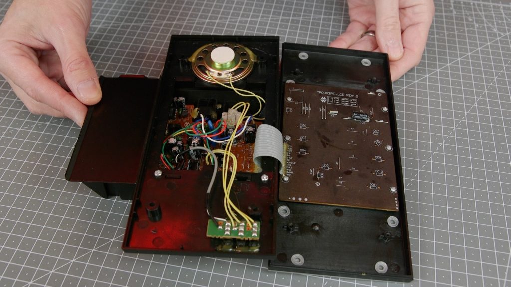
I dismantled the main part of the telephone. Inside I found two PCBs. One had many discrete components: electrolytic transformers, a couple of small IC’s and a transformer. The second board under the keypad had very little on it – just one of those IC’s under a blob of epoxy. The silk screen markings on this board showed that it was responsible for generating the DTMF dialling tones. It also clearly dealt with the LCD display, the keyboard and other dialling features such as memories.
The hook switch (on which the handset sits when not in use) was likely just dirty and so I gave it a few small shots of contact cleaner spray, and excessed the switch. Sure enough this got rid of the crackle. I could now gently massage the switch without depressing it, and this did not generate a crackle.
I think this is the most likely cause of some problem with broadband speed as if the phone circuits kept rapidly switching on and connecting the mic to the line, spurious signals may have resulted. This is just a theory! It may be of course that the crackly phone had no bearing on the poor broadband speed. Certainly I don’t remember hearing any crackles when I spoke to my parents. It should be said that the Jacob Jensen T3 was hardly ever used, due to its location in the house. Anyway, it was certainly a faulty device and that required some attention.
Faulty Ringer
Having come up with two quick and easy wins, this fault required a bit more analysis.
There were rather more components on the main PCB that I was expecting. I couldn’t find a circuit diagram, so had to use some basic principles to try and locate the area of the board with the fault.
I know that telephones usually have a hefty capacitor to filter off the ring signal. There was only one such capacitor on the board.
I had also assumed that some sort of IC was required to generate a nice ring signal. The phone company signals that there is a caller by putting a 75V (RMS) AC sine wave at 25Hz on the line. This is potentially hazardous (especially to those with a weak heart) so care must be taken. It is also not suitable for driving a loudspeaker directly as the frequency is below that of normal hearing. In the old days, it just exercised a bell which would of course generate its own tones even though it had been cycled at 25Hz.
Next to the “big capacitor” was an IC. I couldn’t find a data sheet, but found one for another 8 pin “telephone ringer” device. This had an example circuit which looked rather like the one on the board:
- bridge rectifier to cope with reversal of the line signal, and to rectify the ring signal
- output signal on pin 8 (I’d traced this pin to the ringer volume switch, transformer and loudspeaker)
- some resistors and capacitors across other pins
This IC detects the ring signal, then generates a signal comprising two tones. The frequency of these tones is set by resistors and capacitors across certain pins.
I rang the phone from my mobile, and probed around with the ‘scope. I could see the AC ring signal clearly (note the scope is in AC coupled mode, the -50DC also present on the line is not visible):
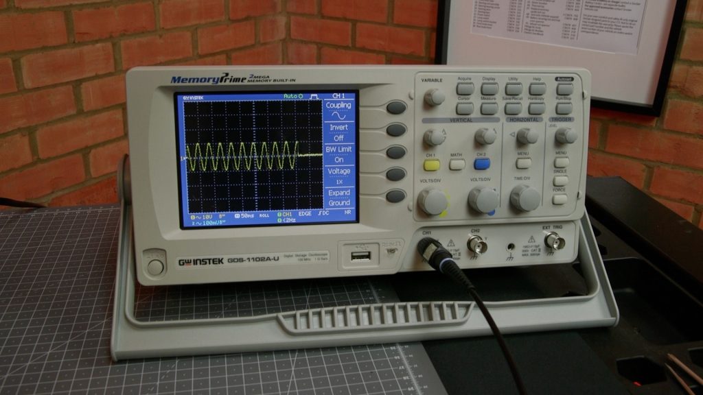
It puzzled me that I was seeing the same waveform on all pins of the IC. I was expecting to see a different signal on pin 8, comprised of some other more audible frequency. However, I appeared to have found the area of the fault. I had a good look around this part of the board. I tried to bend up the ring capacitor in order to inspect some components it was hiding, and in doing so noticed that one of its pads looked damaged. I later saw this in the video footage I’d already shot so I hadn’t damaged it by bending the leg.
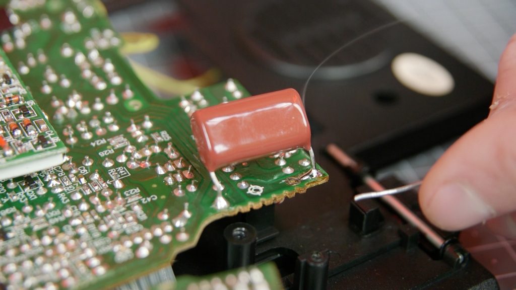
I remade this connection and the ringer worked OK.
Loose socket and clean up
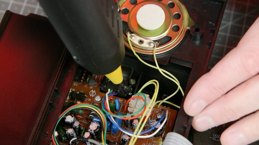
The socket on the rear of the phone that connects to the line was loose. This had been glued into place, and the glue had come away over the years. I scraped off the old glue and applied some hot glue with a glue gun.
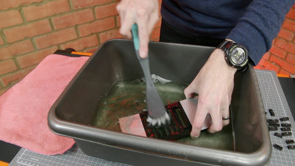
I also stripped down the front panel and gave it a gentle scrub in warm water with a splash of detergent (supermarket own brand “Flash” type cleaner). This got rid of some mild dirt and particles trapped between the LCD and the clear plastic window (always annoying).
Testing
Once re-assembled, it was time for a test call. I’d fitted the workshop out with a telephone extension for this project, as well as running in a couple of CAT5e cables for good measure.
I called my mum to share the good news about her newly repaired telephone, and she elaborated on the story of her winning the phone, as well as encouraging YouTube viewers to “like and subscribe” to the channel.

A quick little project that had a tie-in with a popular television programme, and gave me a chance to learn a little bit about telephones. Also a chance to try out my new video camera and showcase the red LED up- and down-lighters, that I recently salvaged from a decommissioned television studio. Repair, re-use, re-cycle!