Introduction
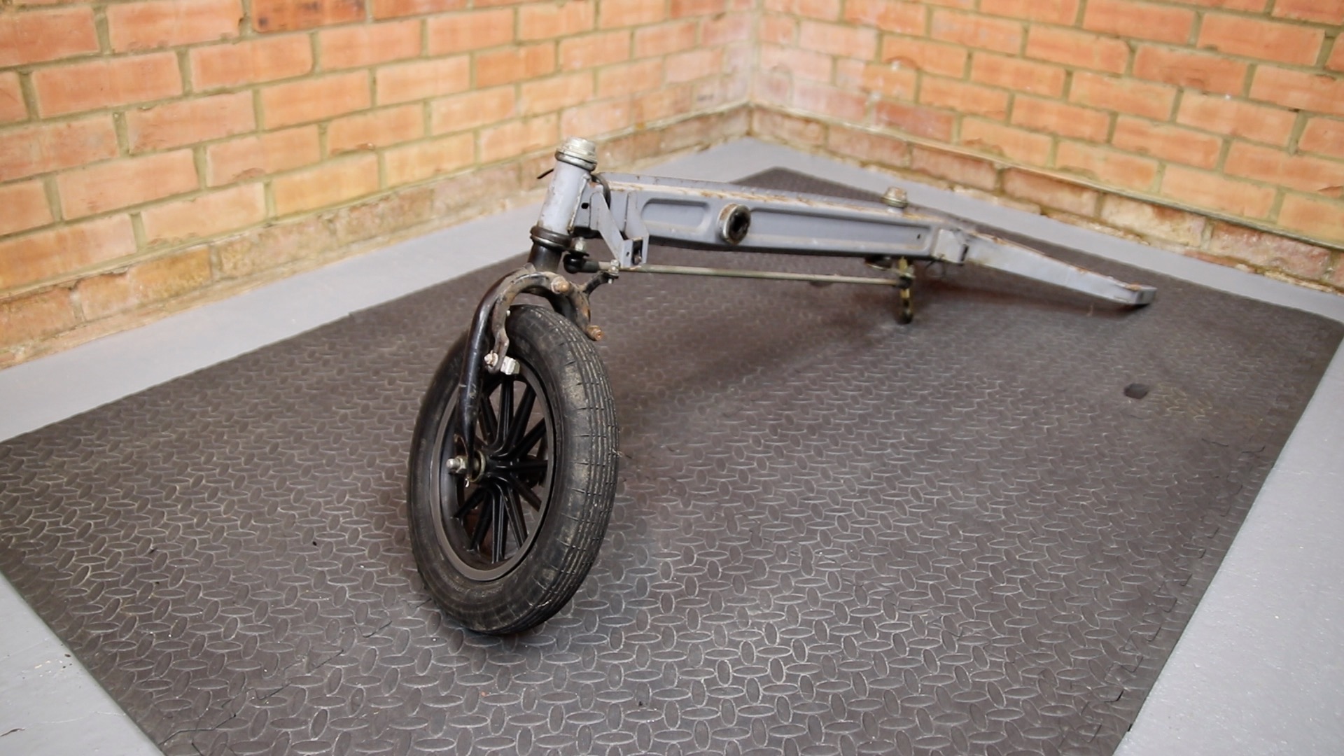
In this second video, I undertake a complete strip down of the C5 to the chassis. This enabled me to inspect the condition of all the parts, and uncover the reason for the wonky wheel. I’ve also noted some new issues such as rust on the chassis and a rear brake problem.
I’m grateful for the users of the Sinclair C5 Owners Facebook forum for all their helpful postings. Special thanks to Charles Snarsky (on YouTube as JORDAN8ISH) for their excellent strip down video (which my video replicates) without which I wouldn’t have known where to start:
Tear down – Step-by-Step Procedure
In this section I document a step-by-step procedure for stripping down a Sinclair C5 to the chassis. It is essentially a transcript of the video. I will update it in future with any tips and updated pictures (for example one image currently shows the incorrect assembly of the rear frame). The intention is that this document can be printed and used in the workshop to assist disassembly and re-assembly.
1) Remove the battery

2) Take out the boot. First remove a horseshoe circlip under each wheel arch

3) Push the wheel arch to one side, then extract the boot
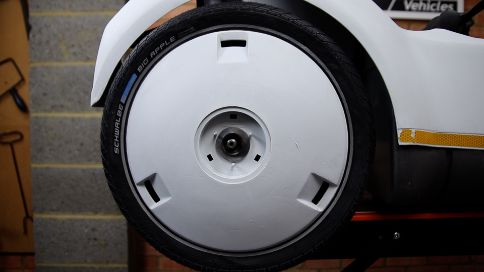
4) To remove the left-hand rear wheel, first remove the centre cap. Push the rear of it from inside the boot area

5) Remove the nut
6) Slide the wheel off
7) Slide off the drive belt

8) Slide of the drive gear

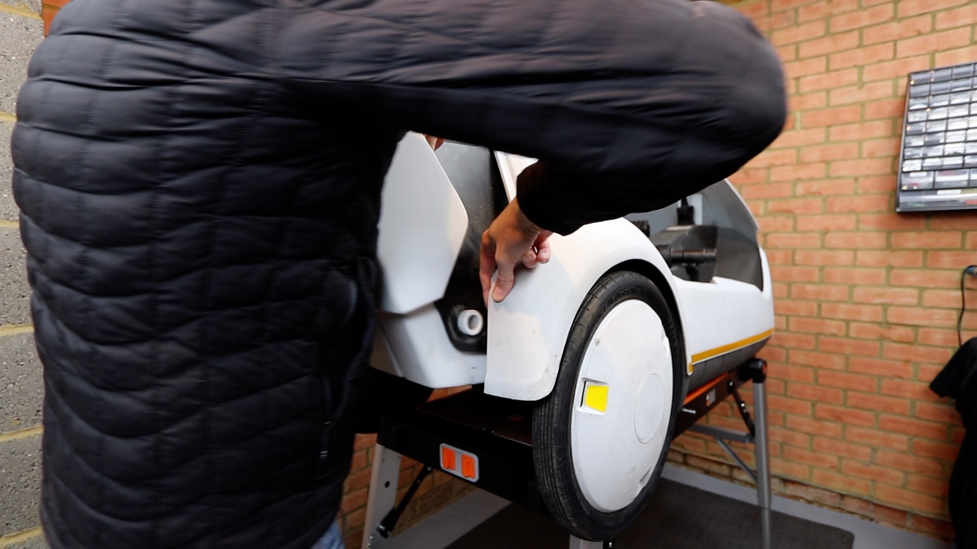
9) Remove the rear right-hand wheel. Start by removing the centre cap, by pushing it from the inside

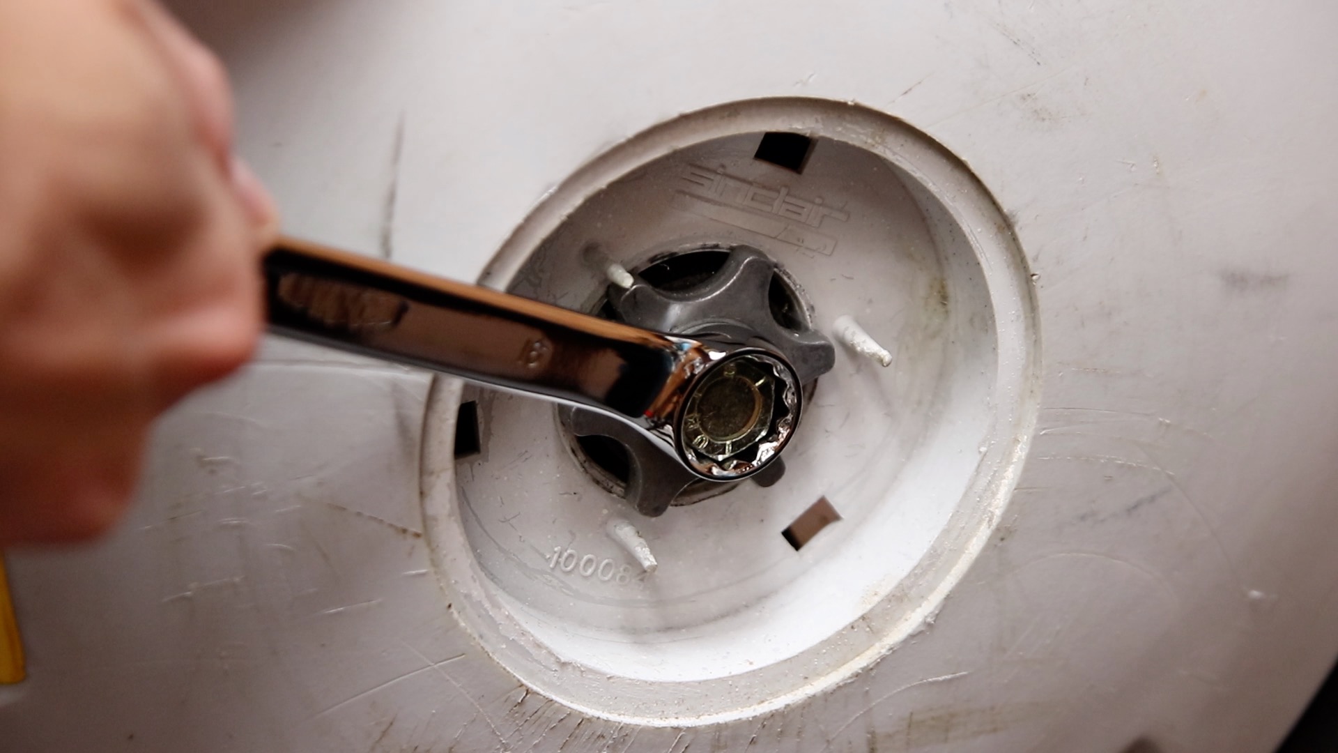
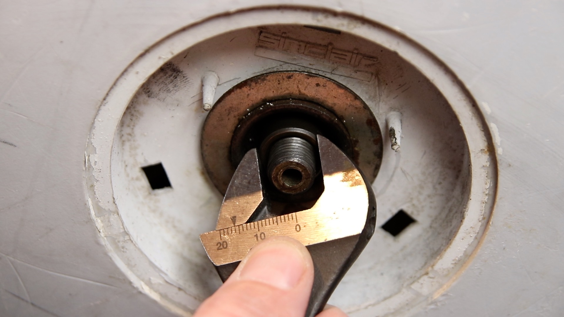
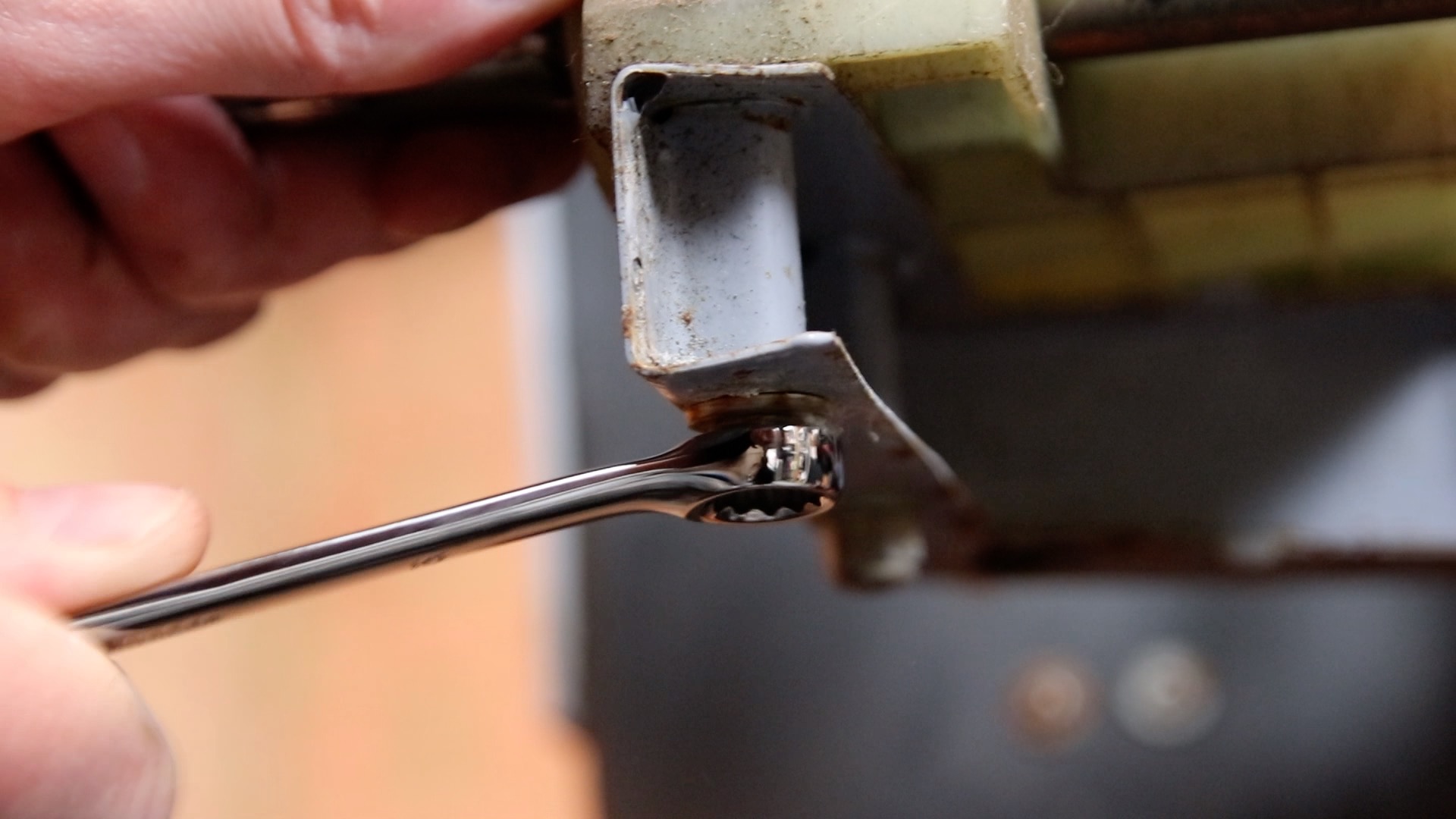
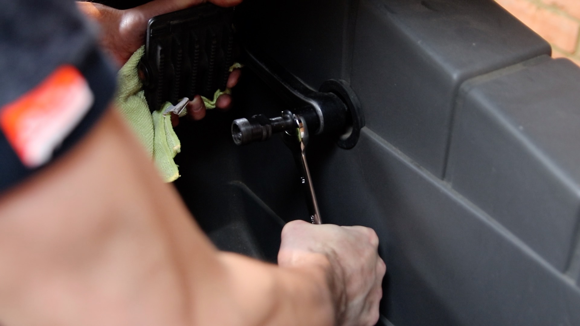
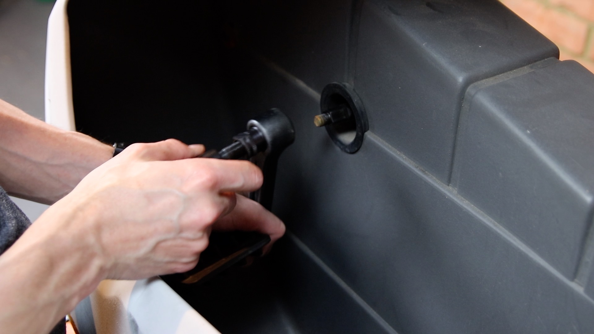
10) Remove the outer nut

The outer nut is a locking nut that holds the inner cone nut in place. There is a special tool that comes with the Sinclair tool kit (which originally shipped with every C5). This tool allows you to hold the inner cone nut in place, whilst tightening the outer locking nut:
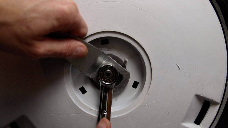
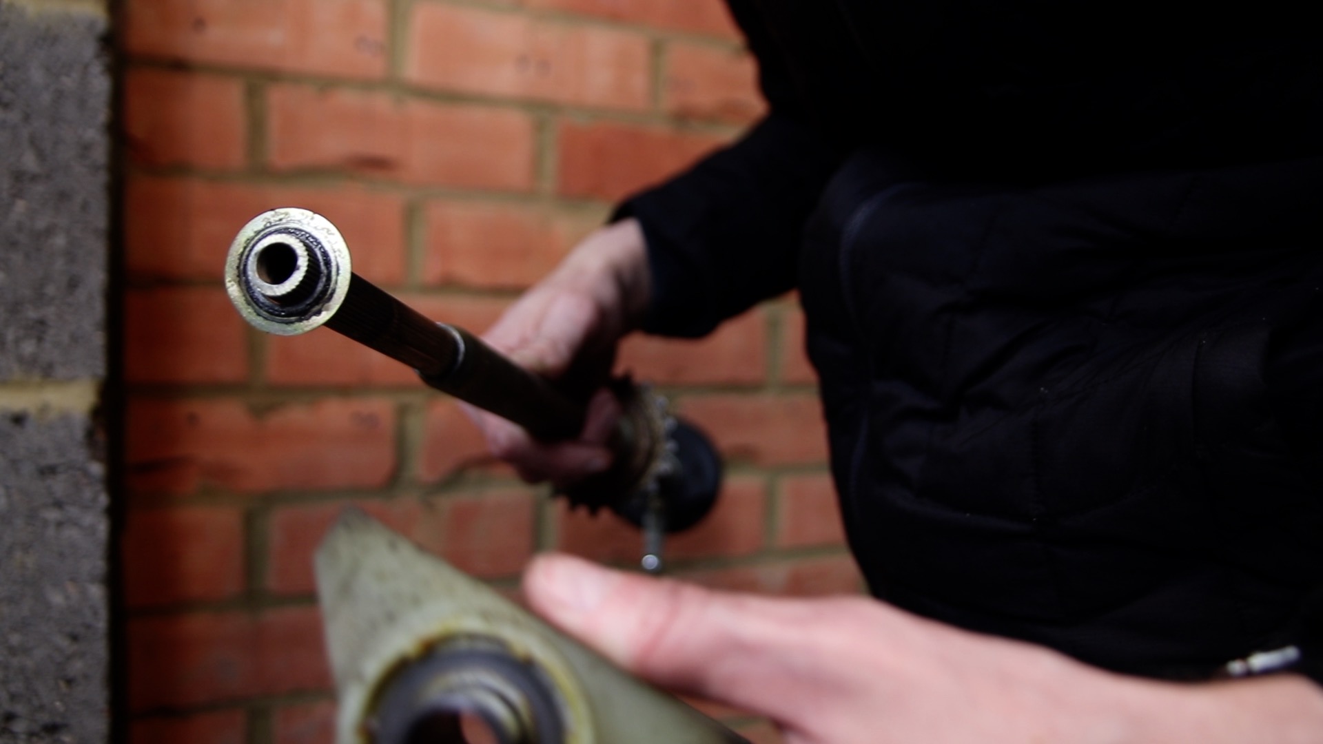
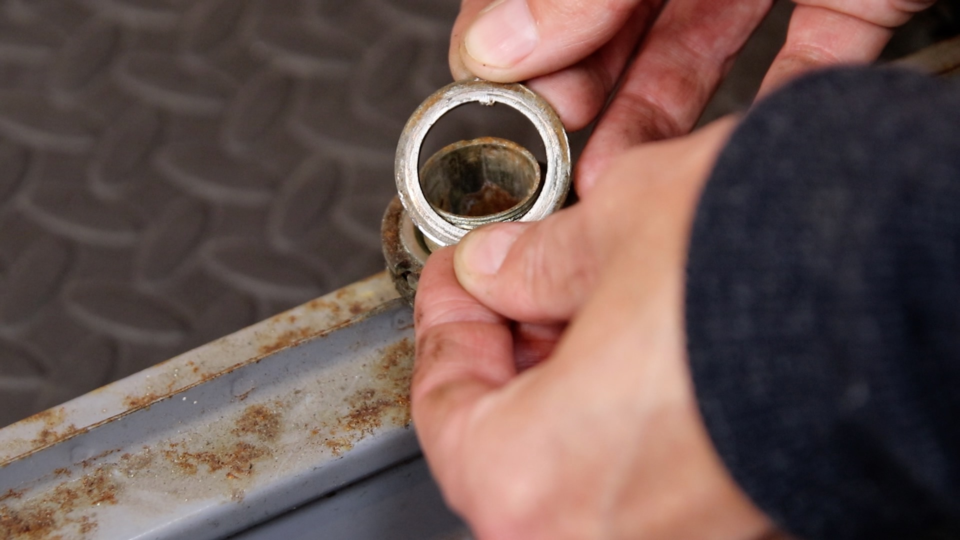
11) Remove the inner cone nut
In my video (part 2), the bearings are shown in the wrong position as it was like this when I bought the C5. The correct order is shown here (as shown in video part 3).
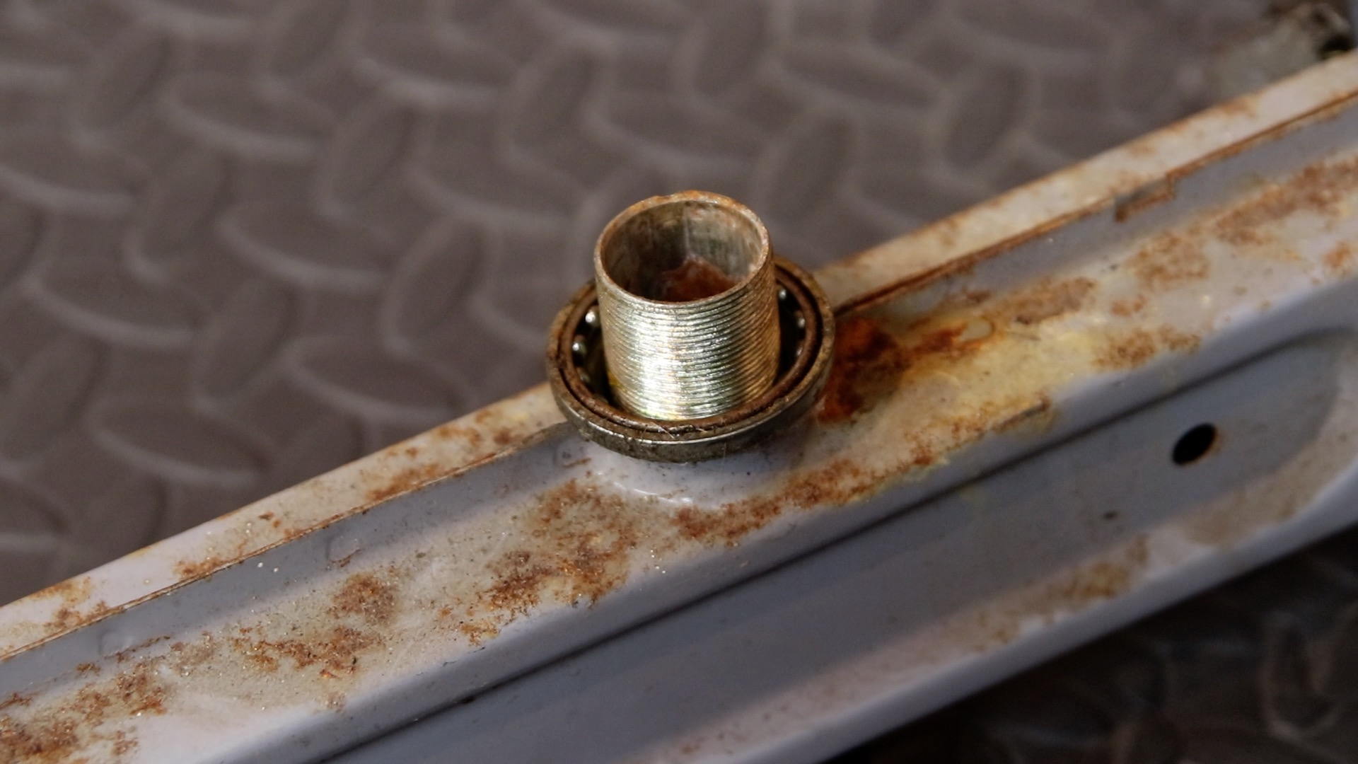
12) Remove the outer bearing. This sits with the wider side facing towards you.

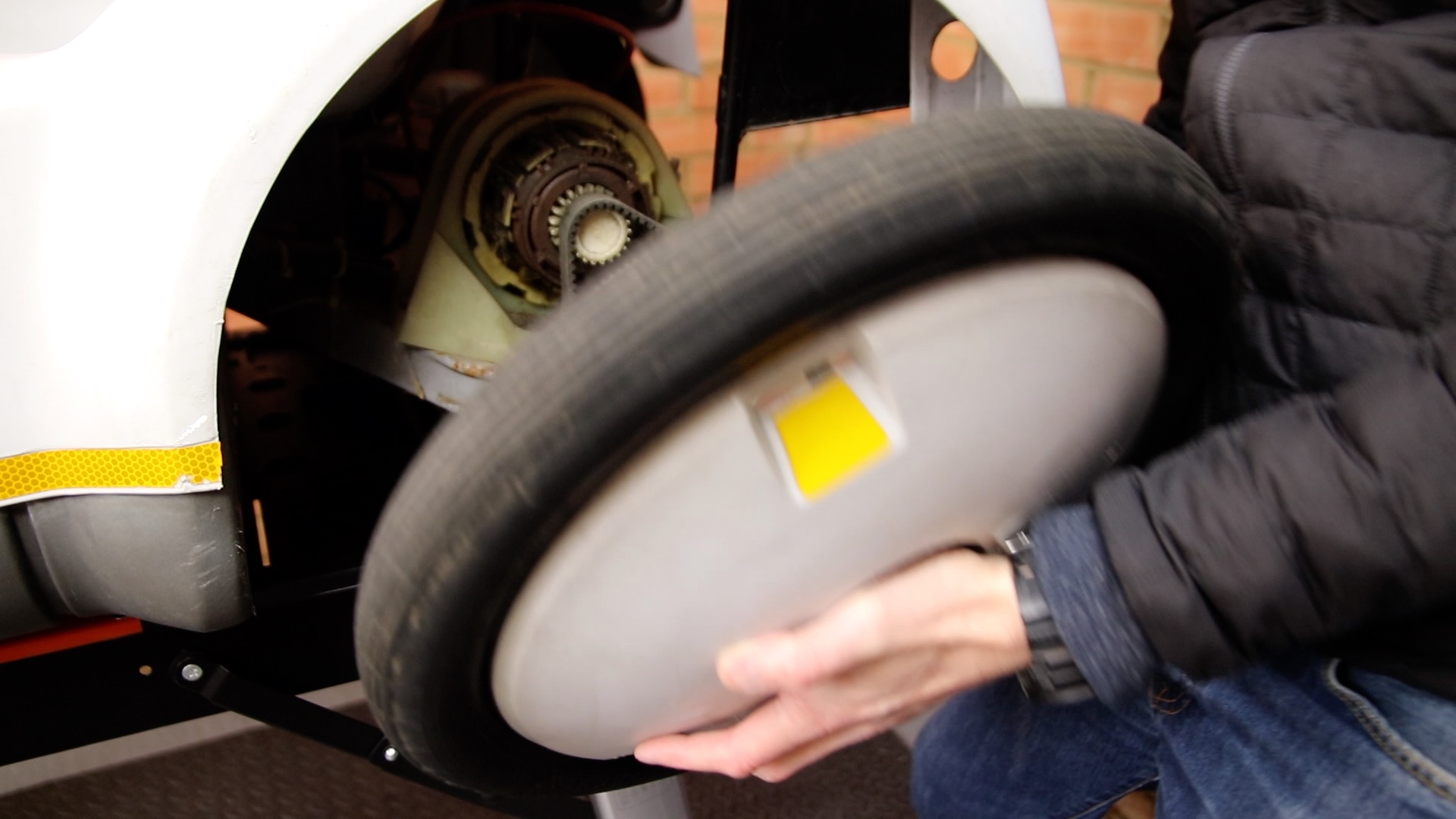
13a) Remove the wheel. The outer cup and large washer will come off with the wheel (the bearing sits in this cup)
13b) You should now see the inner cup, in which the inner bearing sits
13c) Remove the cup and bearing (again, the bearing sits in the cup with the narrower part in the bottom of the cup). Inspect the bearings for damage
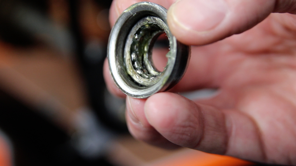
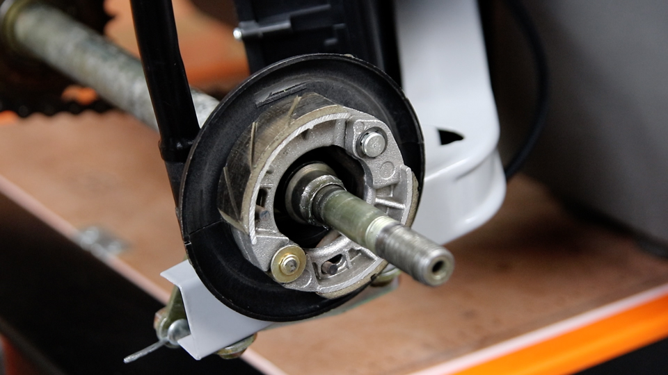
14) You can now see a cone shaped piece on which the bearing sits, which sits on the axle. This can slide off if required. Check the rubber on the rear drum brake pad for wear
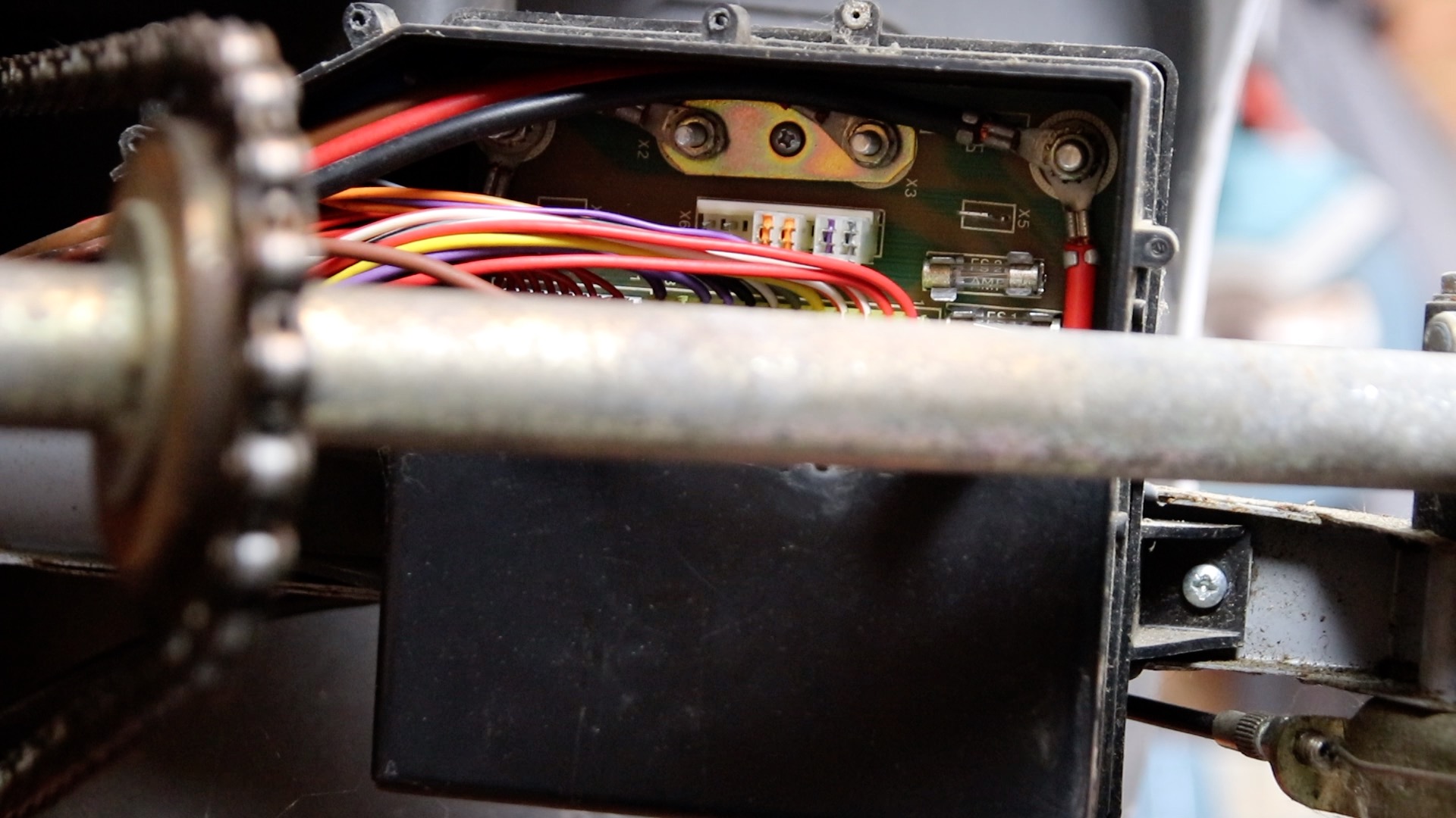
15) Remove the cover from the Control Box

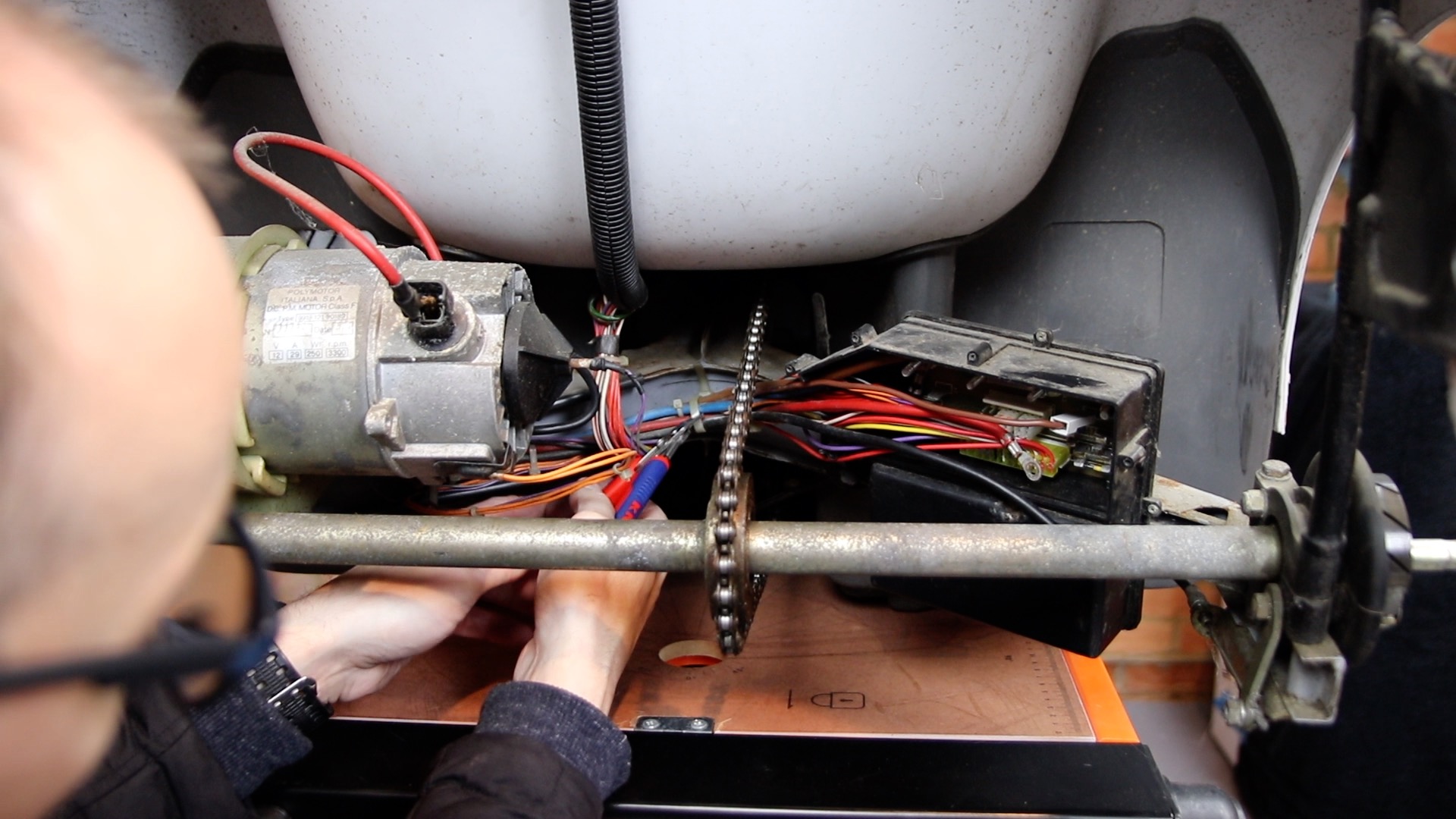
16) Remove the bolts fastening the black and red motor cables to the PCB
17) Carefully cut the cable ties holding the wiring loom onto the chassis
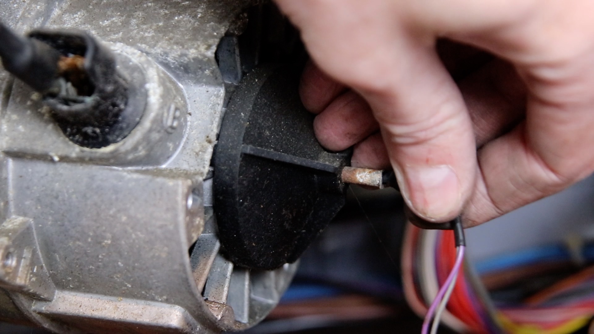
18) Unclip the thermal trip switch from the body of the motor

19) Pull the thermistor out from the centre of the motor
20) Loosen (don’t remove) the nut holding the motor

21) Slide the motor out to the right and set it carefully aside. There are many fragile plastic parts on the motor

22) The boot area looks a lot more spacious

23) Remove two screws holding the rear lamp holder
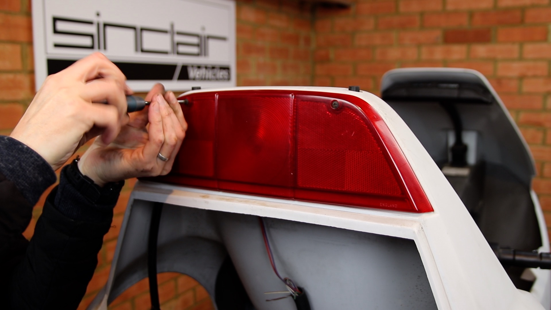
24) Gently pull the lamp diffuser forwards to reveal the lamp holder and wires. Carefully work the lamp holder free. If the rubber is stiff, a gentle side to motion whilst pulling helps to free it
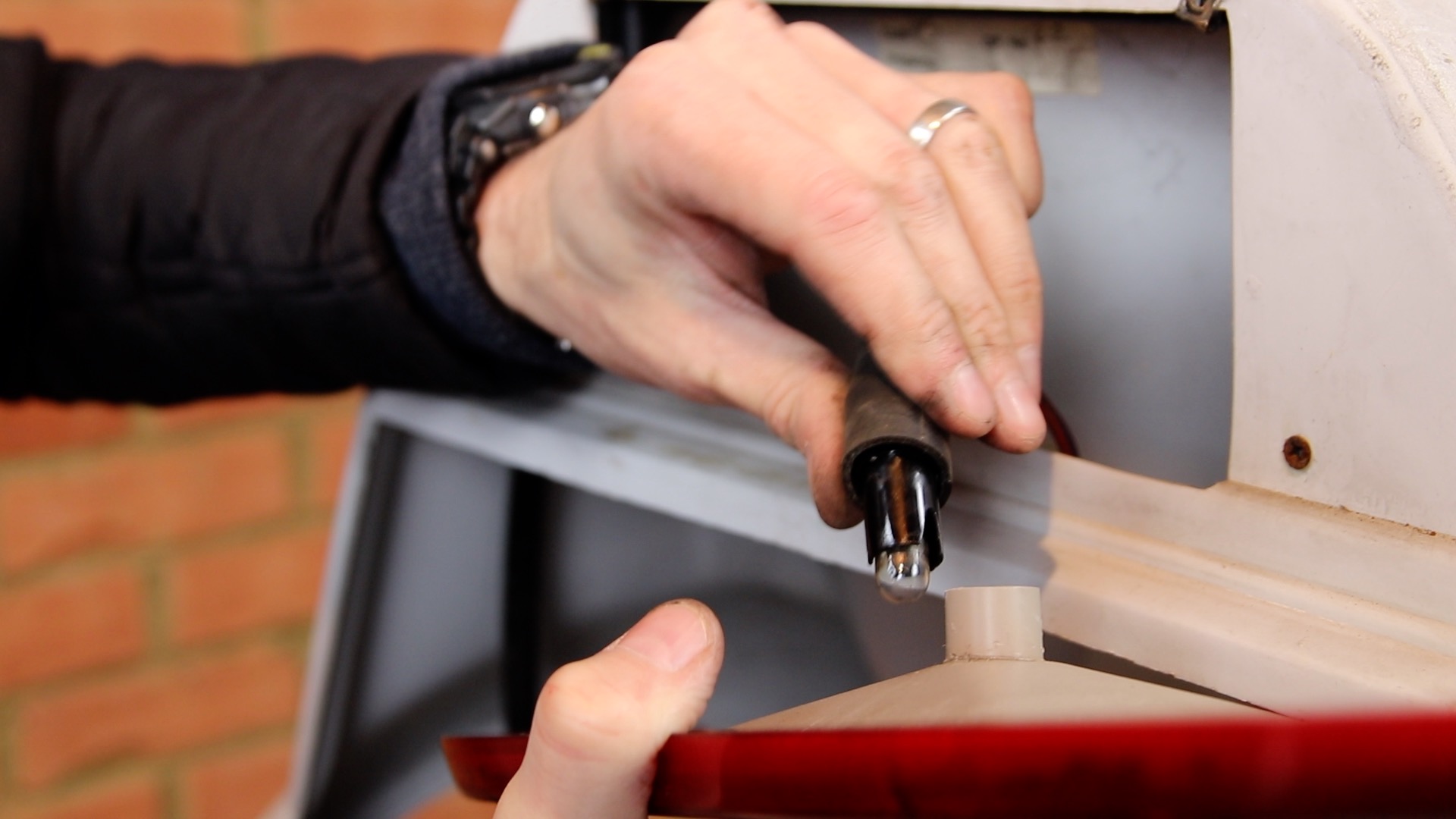
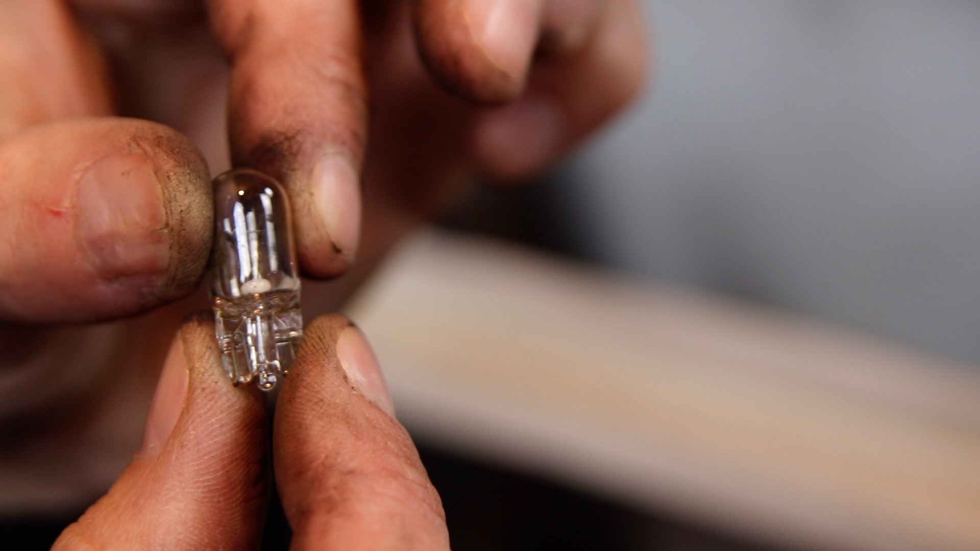
25) Pull out the lamp. You should avoid touching the glass if it is an original filament lamp as shown here. Use a cloth or nitrile gloves. If touched, the glass should be cleaned with alcohol or white spirit to remove grease, otherwise premature lamp failure may occur. You may replace with LED lamps which are lower power and can be touched without caution.
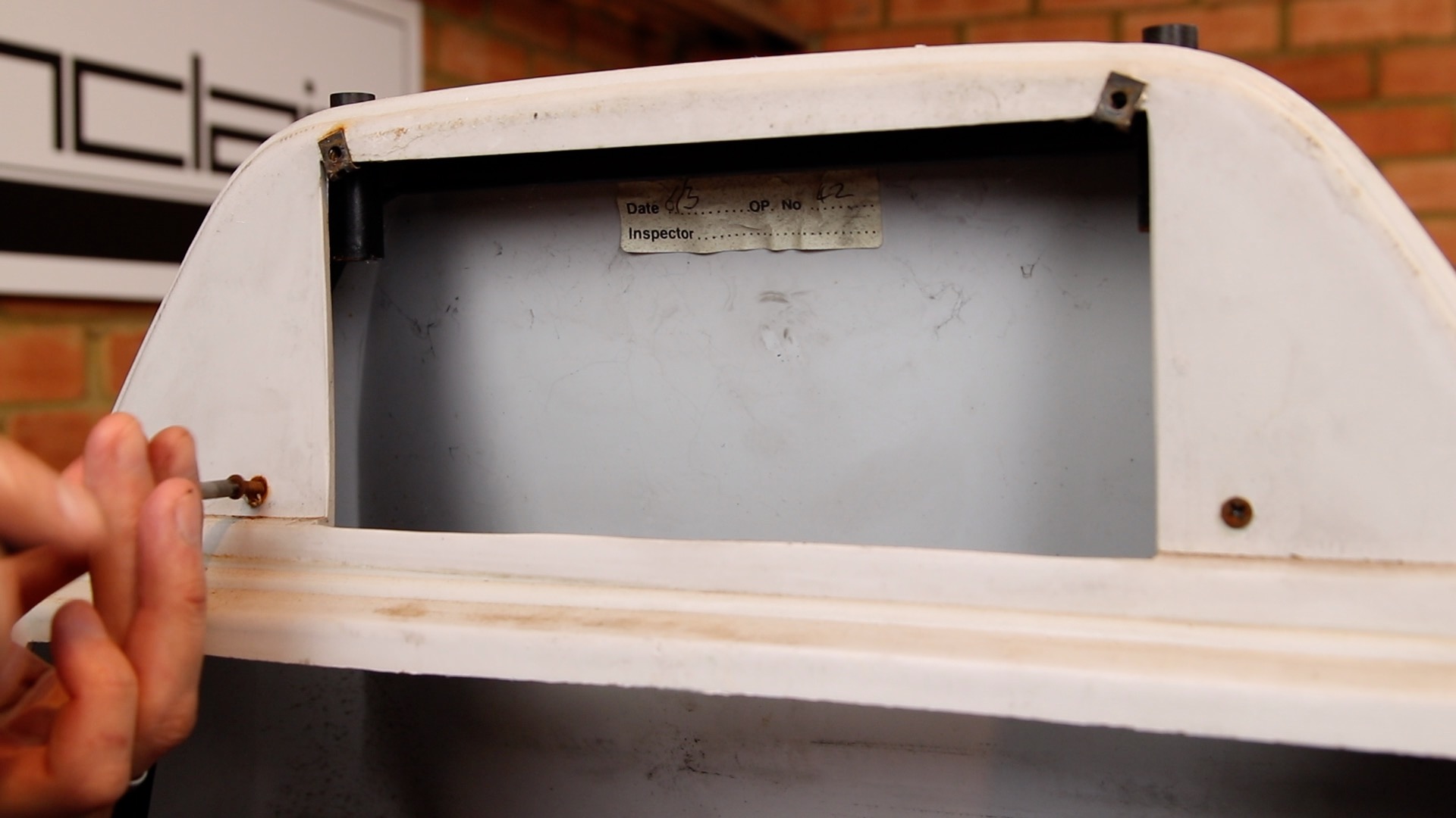
26) Remove two screws that attach the body shell to the rear location frame
27) Remove the bolt on the rear, left-hand side of the chassis that connects the chassis to the rear location frame
28) Remove the bolt on the rear, right-hand side of the chassis that connects the chassis to the rear location frame

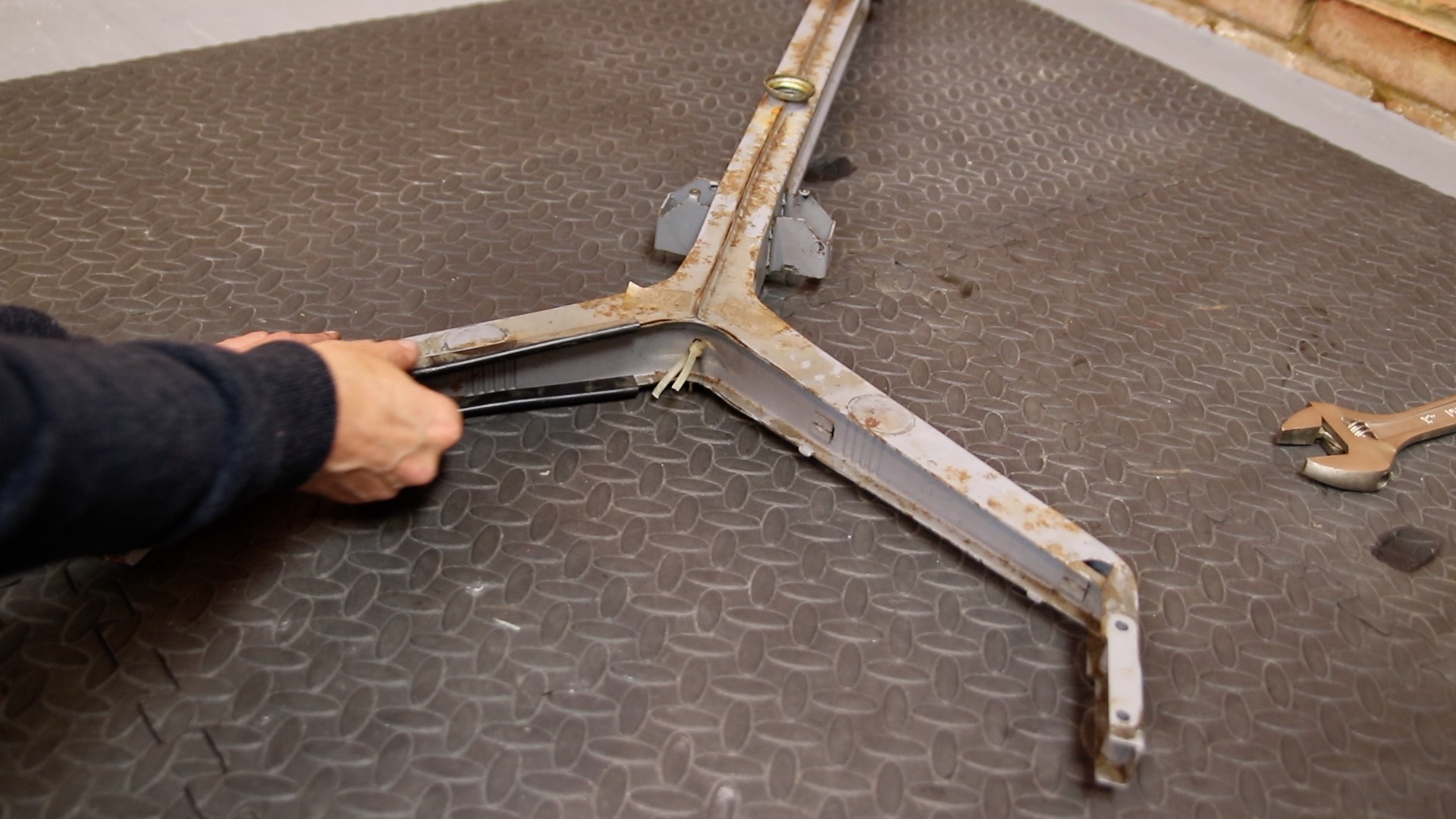
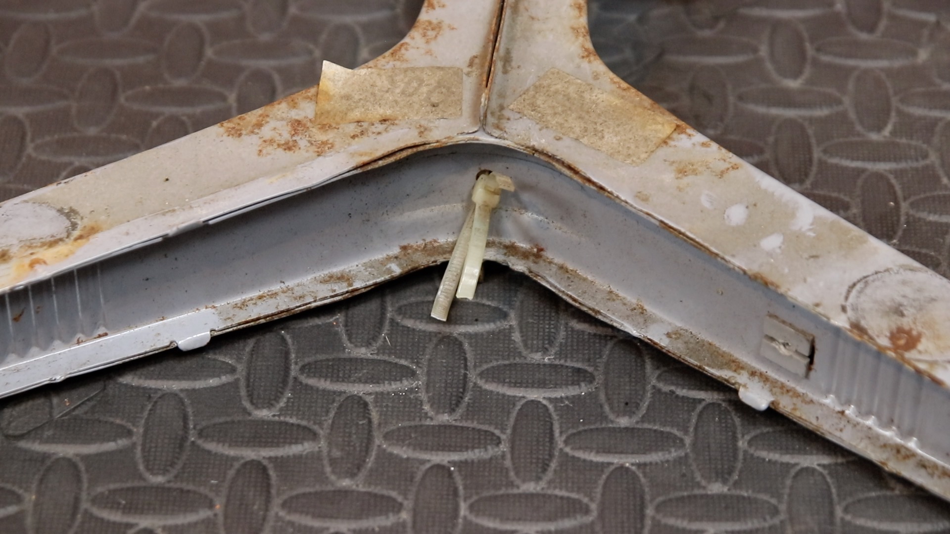
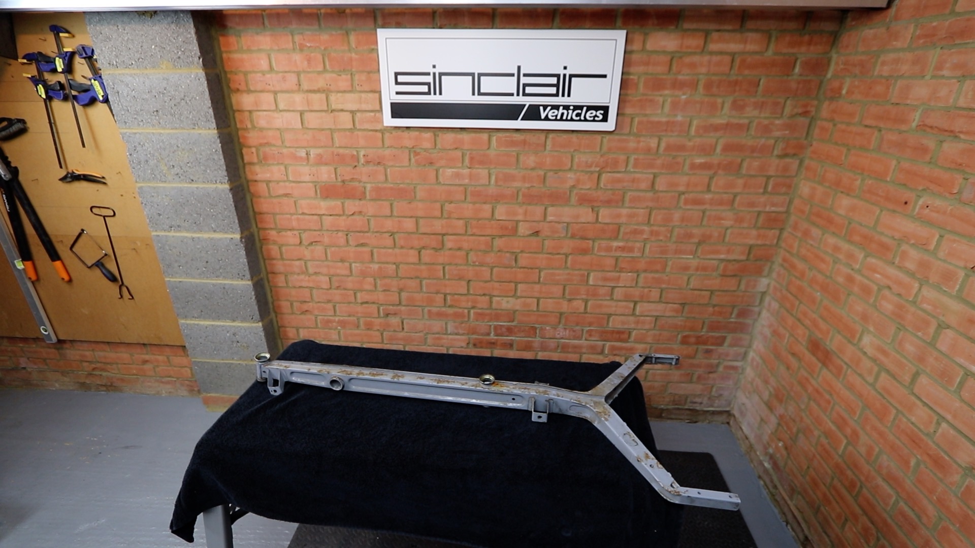
29) Remove the rear location frame

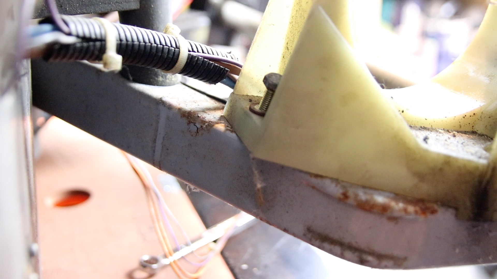
30) Remove the middle bolt that fixes the motor support to the chassis
31) Remove the metal plate. This plate is a retro fit from Sinclair Vehicles that prevents the plastic tongue from bowing out, and therefore stops the motor from tilting (see here for more info)

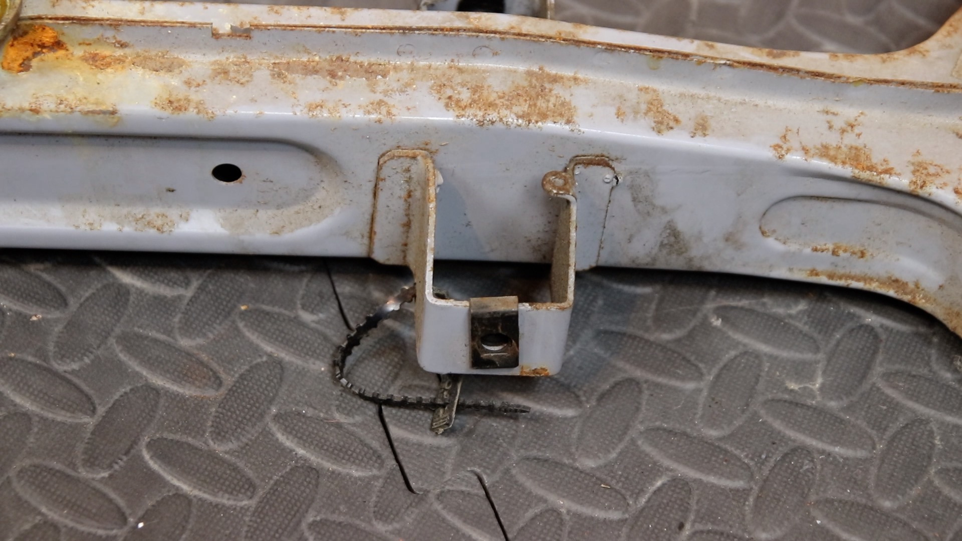
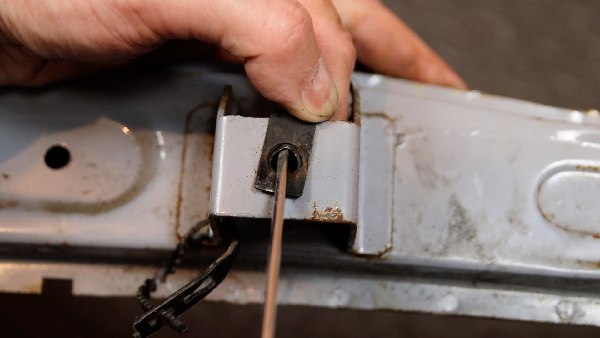
32) Remove the front bolt from the rear brake assembly

33) Remove the nut on the rear brake cable

34) Remove the rear brake cable

35) Remove the rear brake fitting

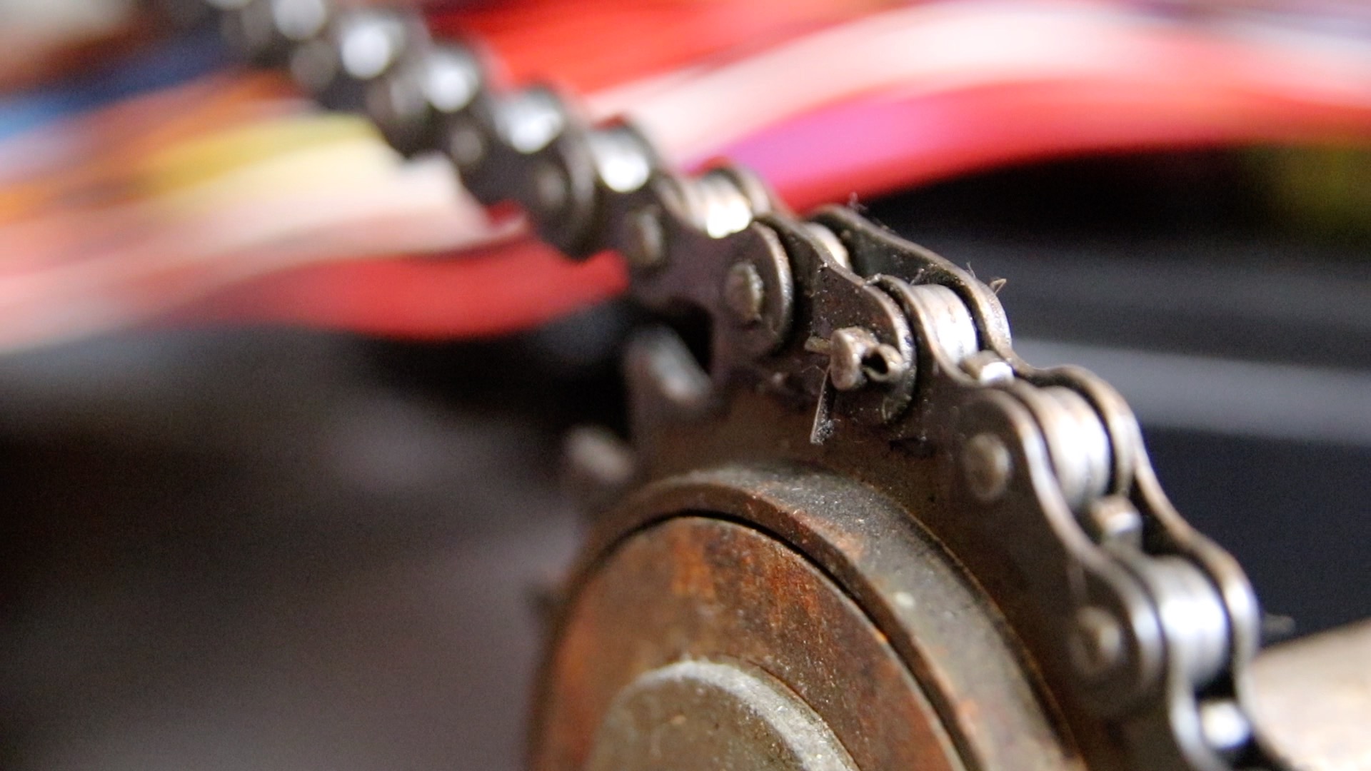
36) Locate the split pin in the chain
37) Straighten the split pin with some fine nose pliers, and remove it
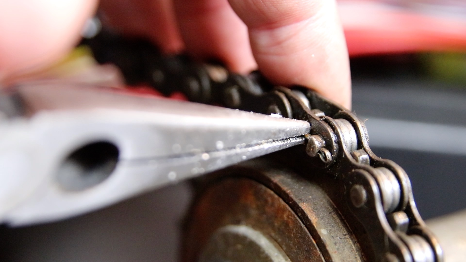
38) Remove the chain link. The chain will come apart. Remove the chain

39) Remove the front bolt on the motor support
40) The rear axle is now free for removal
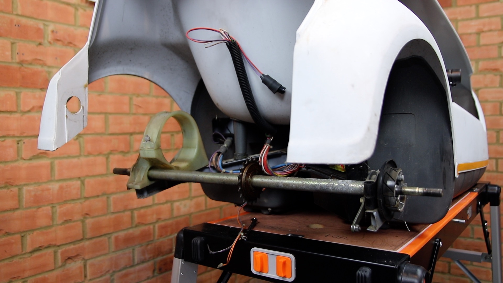
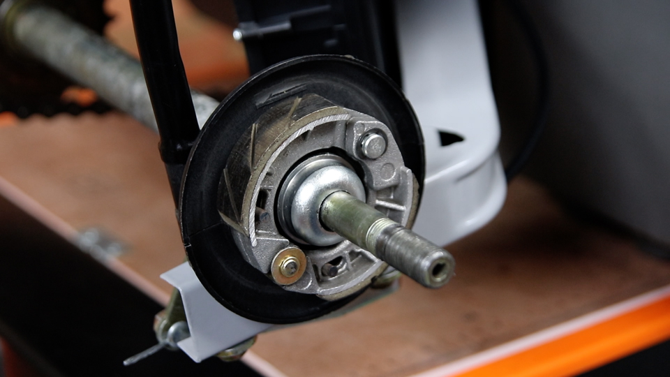
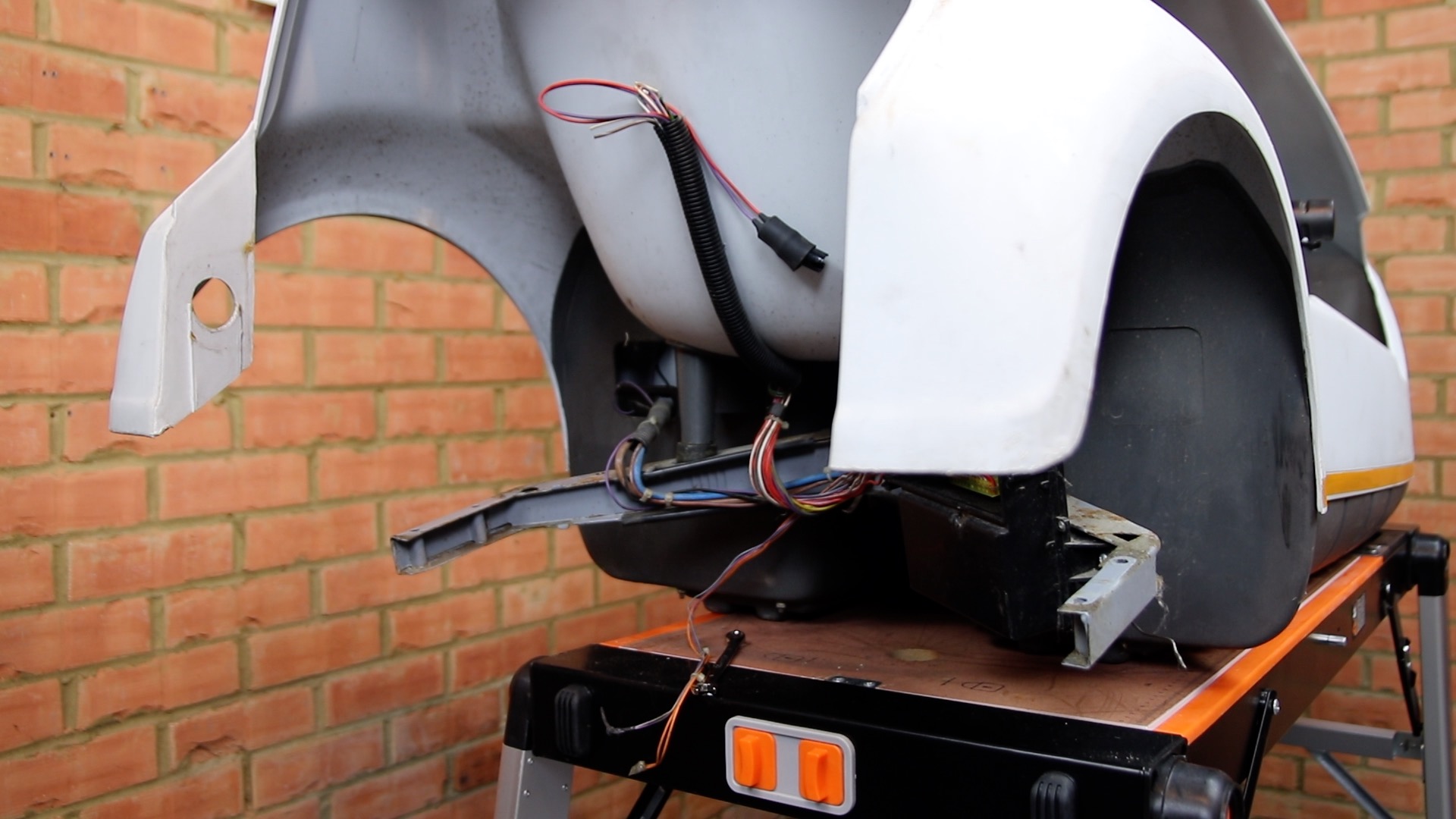
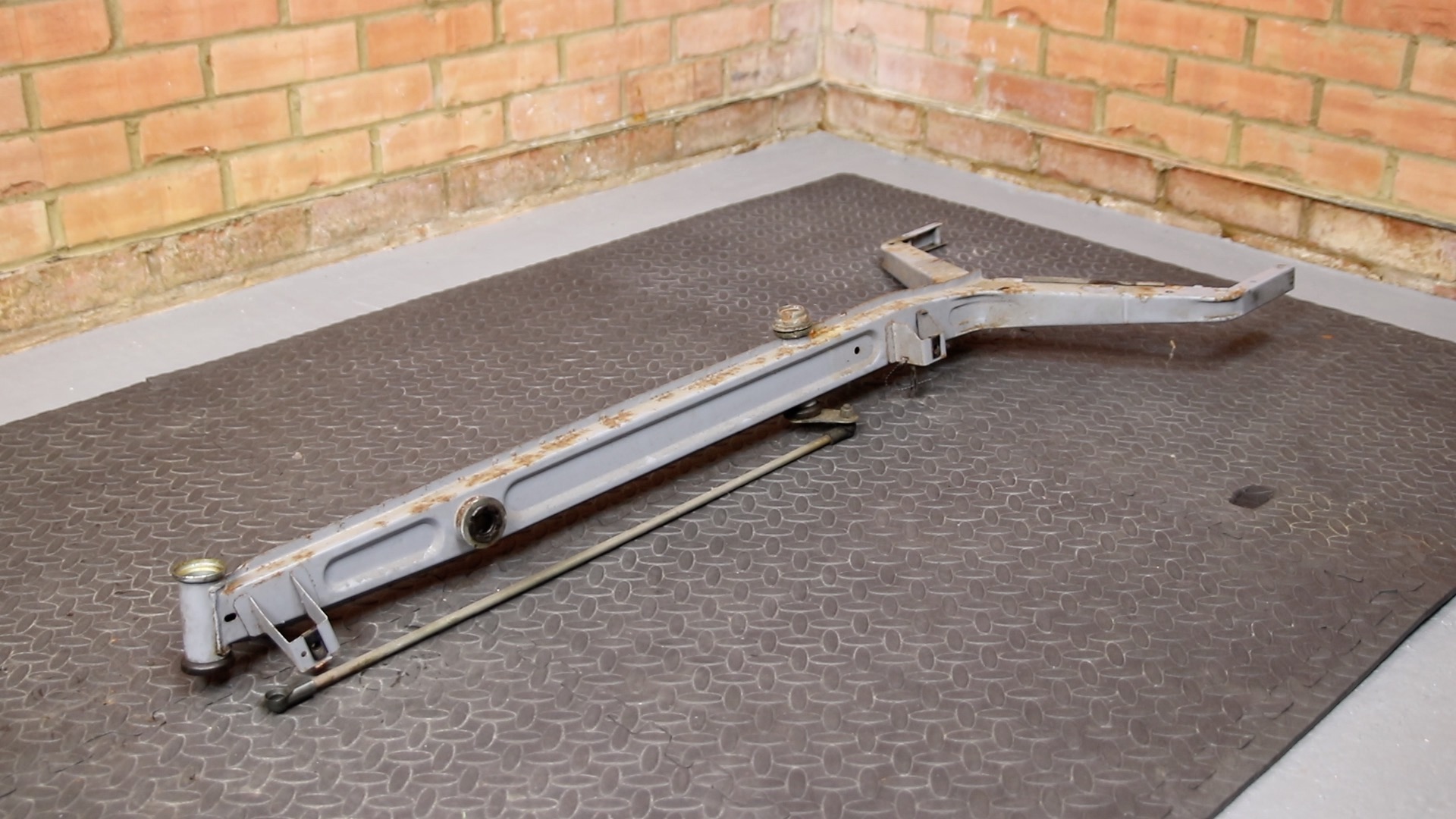
41) Here we see the rear of the C5 with the axle removed
42) Remove the motor support from the axle, taking note of positions of the washers
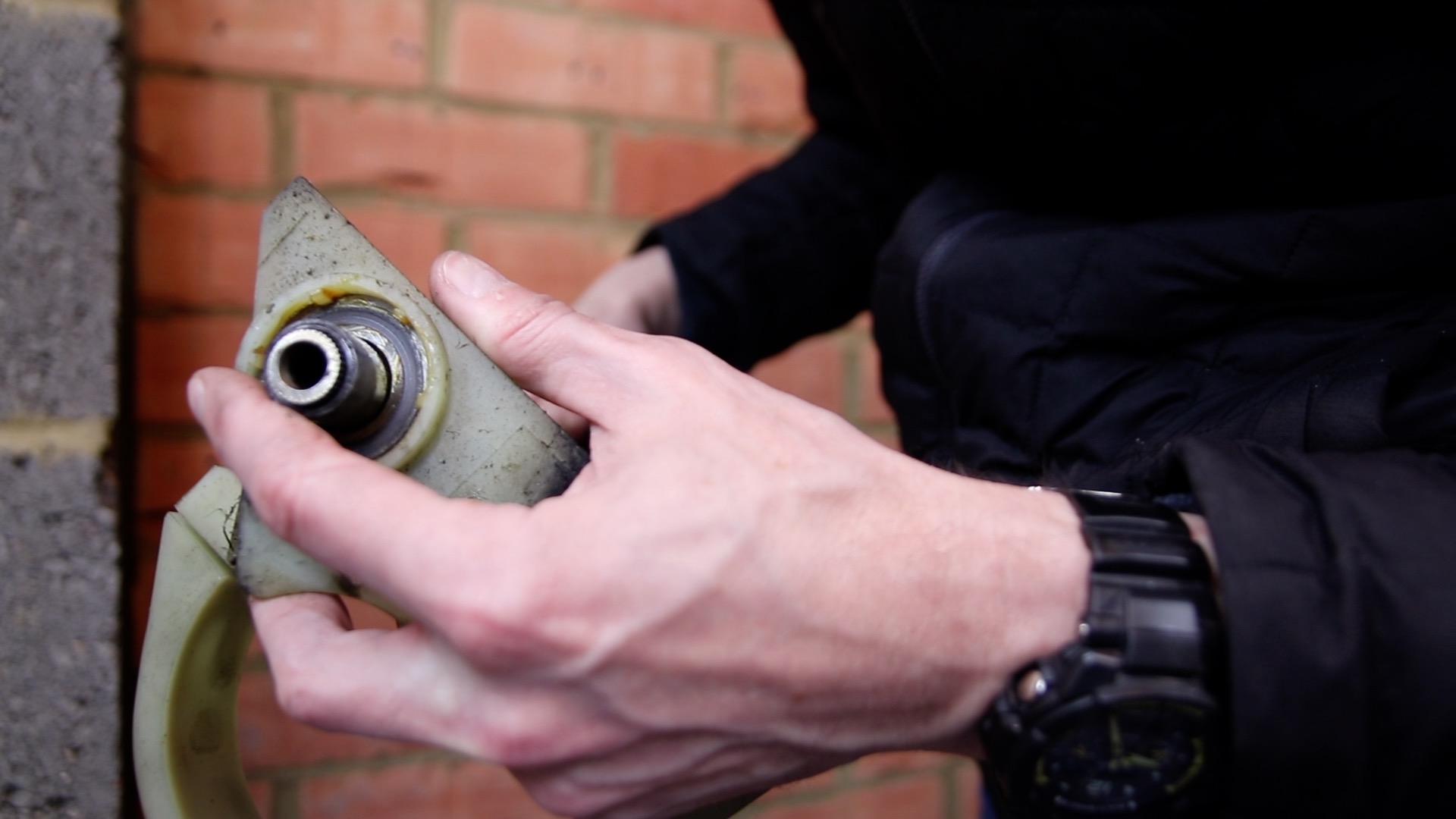
43) With the motor support removed, note the position of the final washer
44) Rotate the freewheel and sprocket. This should turn freely in one direction, and “click” as you turn it

45) Remove the Control Box which is secured by a screw at either side

46) Remove the foam handle bar cover
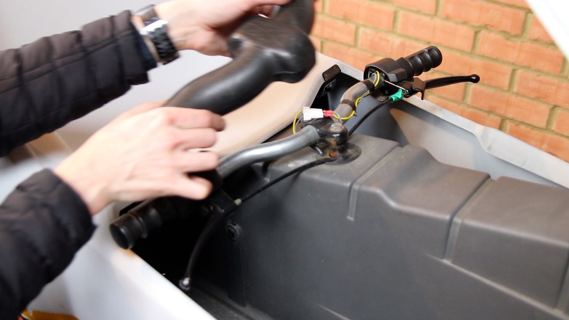
47) Remove left brake lever bolt
48) Remove right brake lever
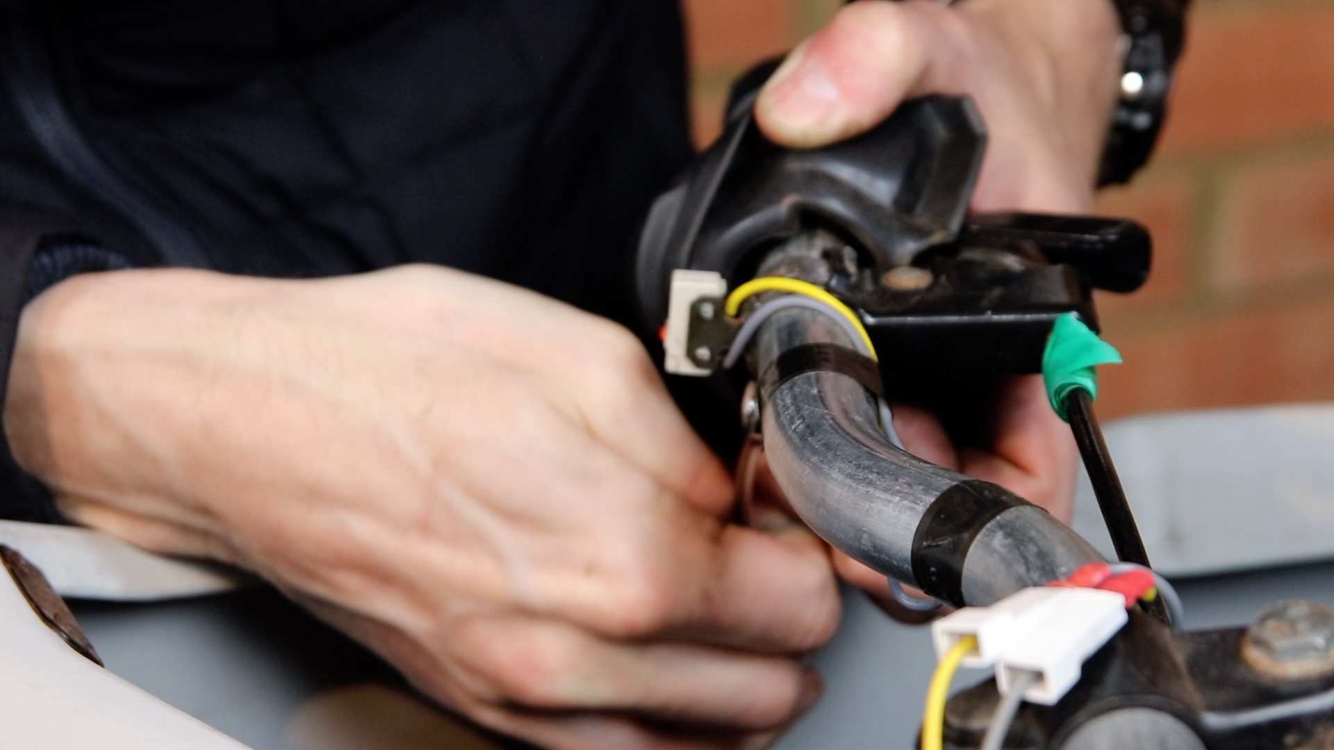
49) Pull apart connectors that feed the motor power switch

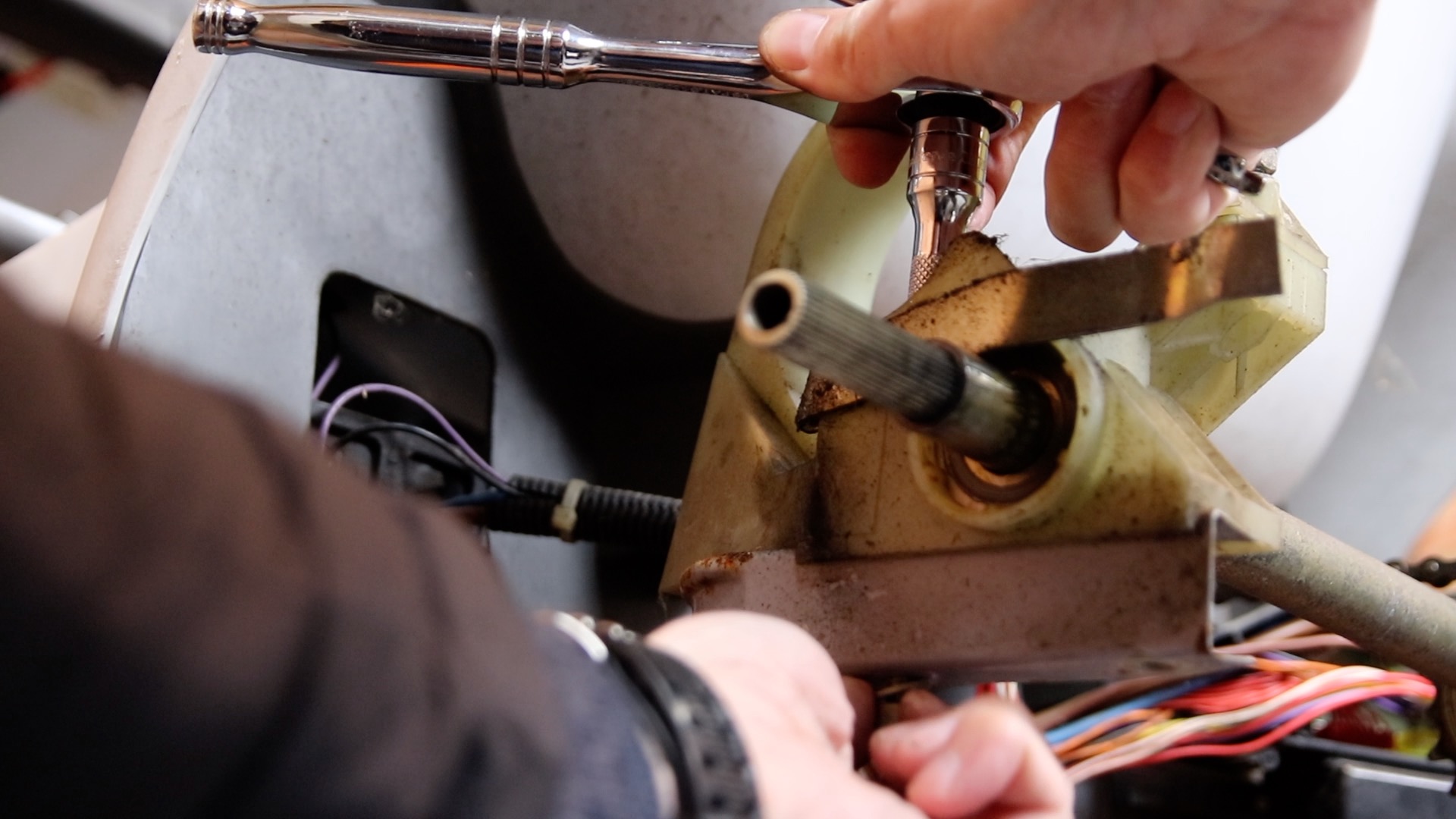
50) Loosen the bolt holding the steering bar. Don’t remove it completely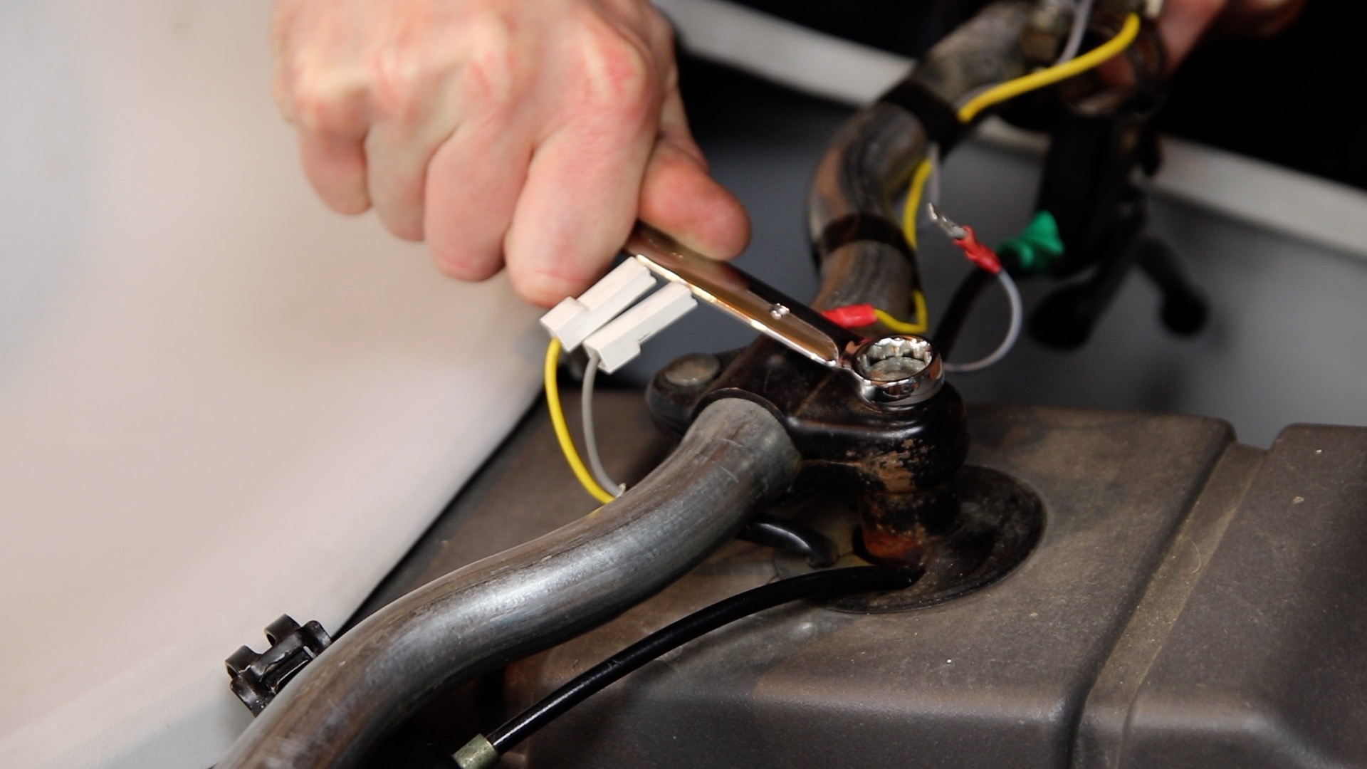
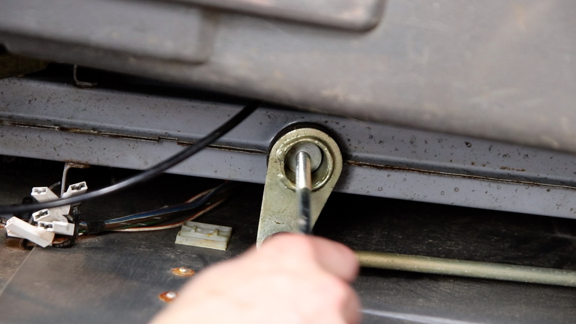
51) Using the end of your screwdriver, bash the top of the bolt. This should knock the cone shaped nut out of the bottom. Then undo the bolt completely
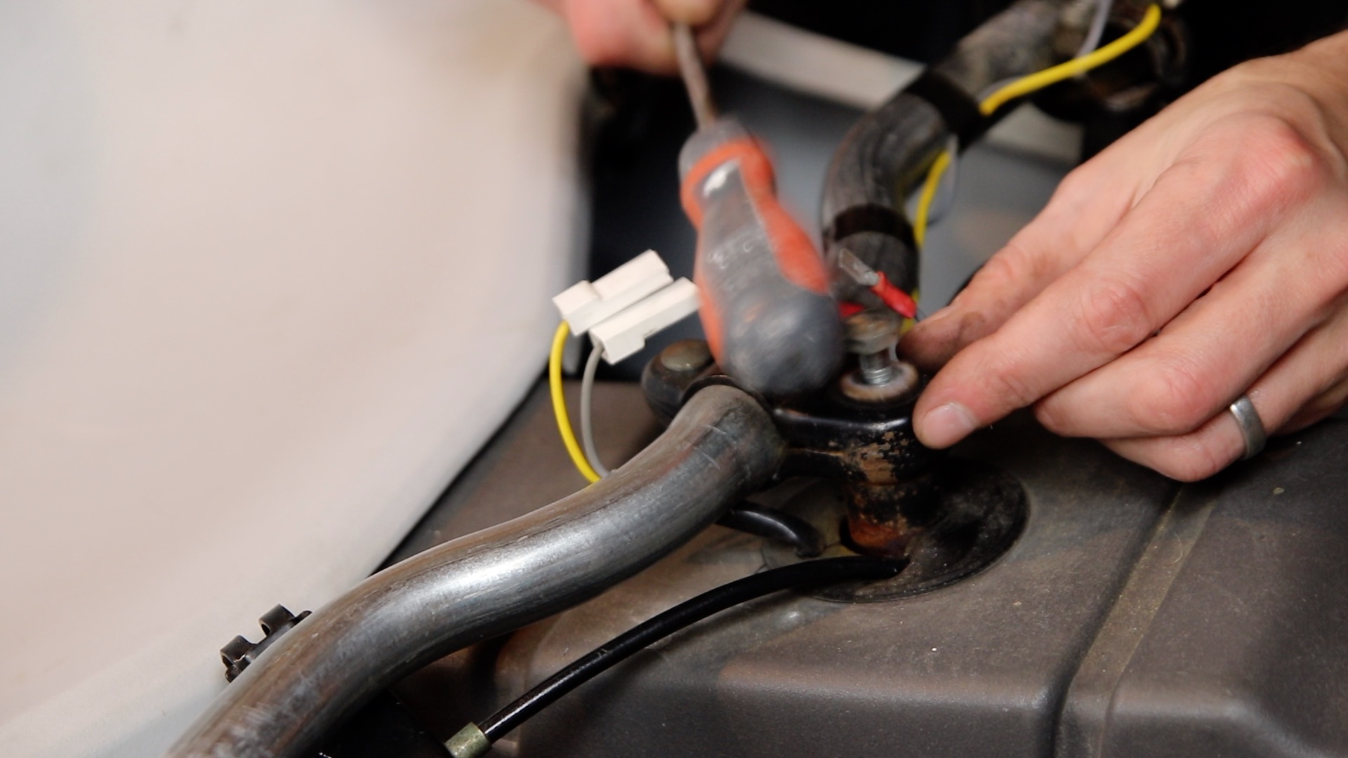
52) If you are struggling to knock out the cone shaped nut: remove the bolt and re-attach it from the underside of the C5. You can now pull it out
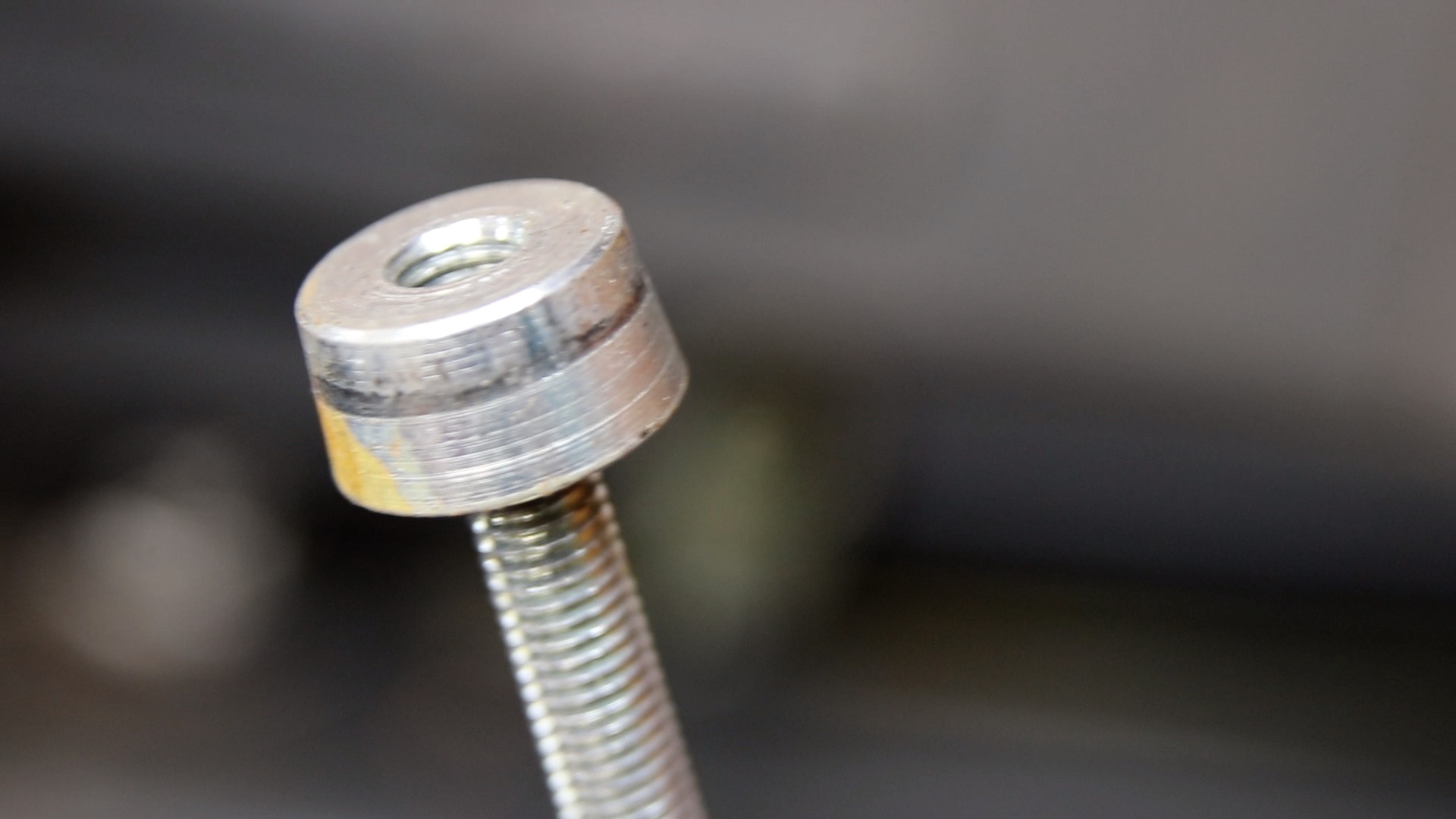
53) The cone shaped nut
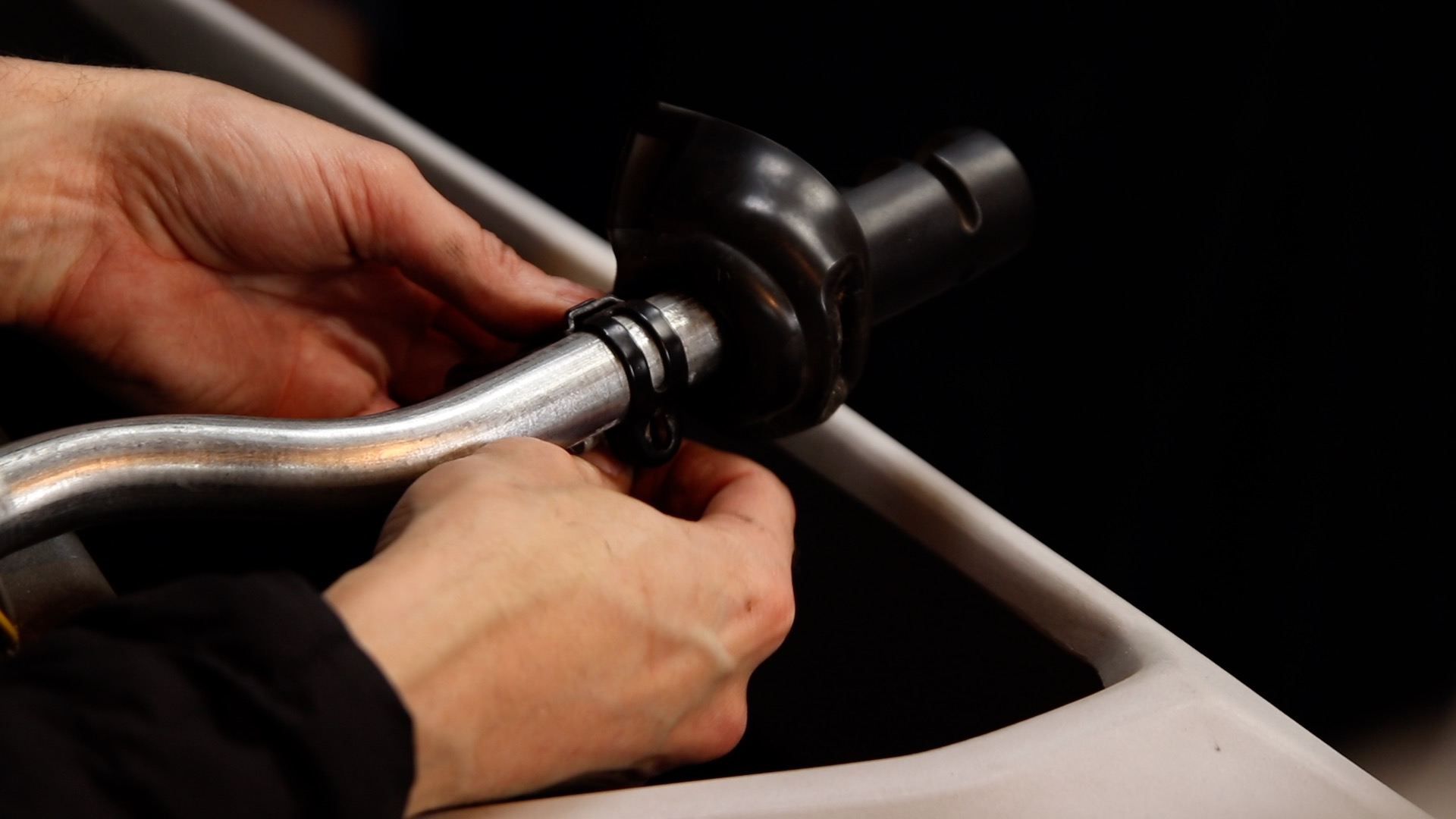
54) You can now work the from side to side, and pull it upwards
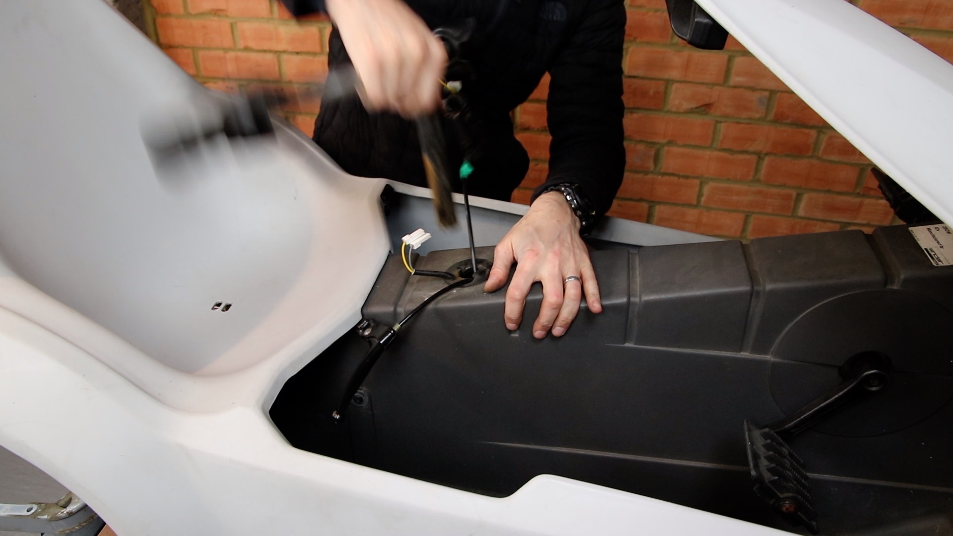
55) Remove the covers to the crank axle

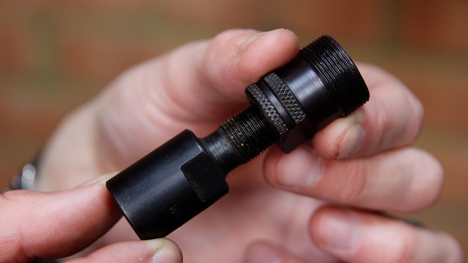
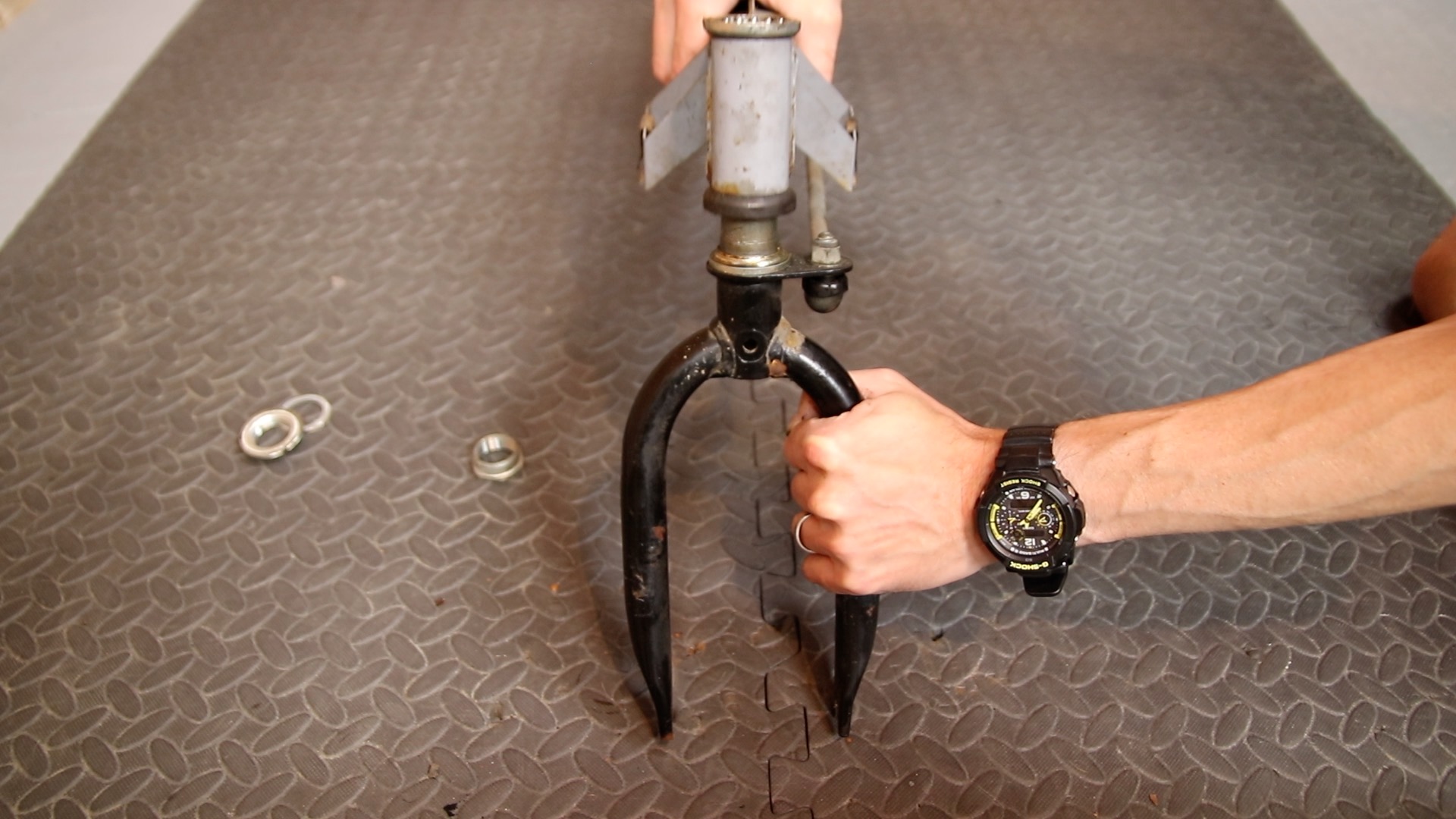
56) Prepare a Cotterless Crank Removal Tool by unscrewing the two parts most of the way
58) We will now remove the right hand crank

59) Push the non-threaded end onto the pedal nut and use a spanner to loosen the nut. This end of the tool acts like a socket to remove the recessed nut
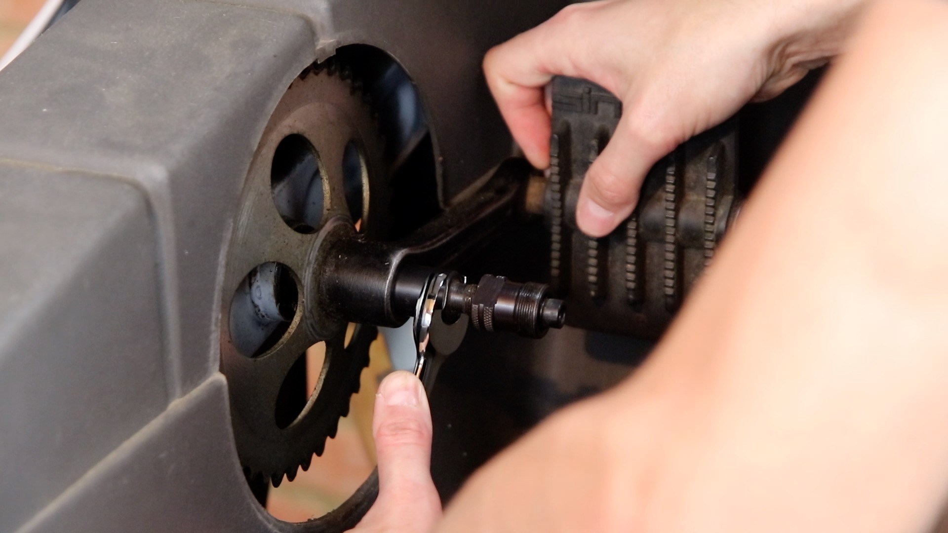
60) With the nut removed, you can clearly see a thread on the crank, into which we will now screw the other end of the tool, finger tight
61) Having screwed in the tool, use a spanner to turn the inner part clockwise. This pushes the inner part against the crank axle and pushes off the crank

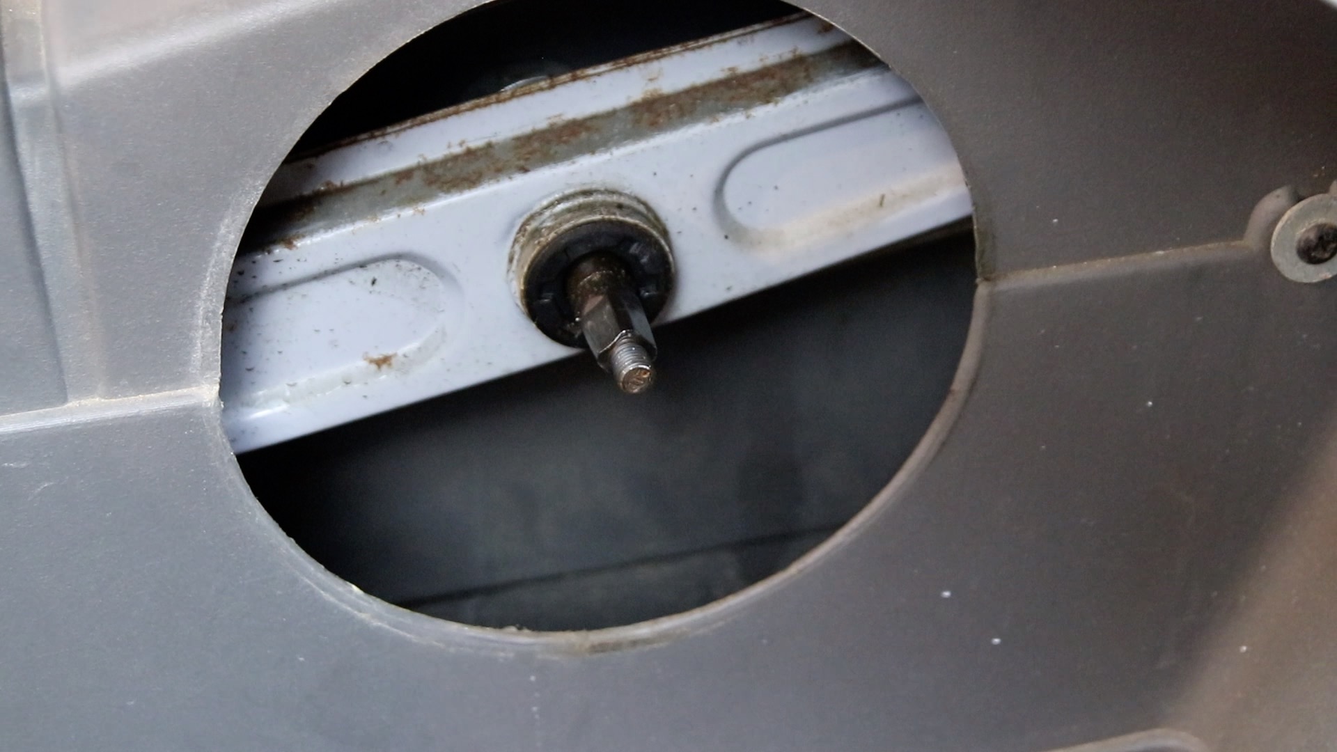
62) The crank will be pushed off to reveal the crank axle
63) Repeat the process on the left crank, by first using the tool to extract the recessed nut
64) Now use the other end of the tool to push against the crank axle and release the crank
65) Back on the right side of the C5, use a large flat screwdriver and hammer to knock the black locking nut clockwise to unscrew it (it is a left hand thread – so clockwise to unscrew)
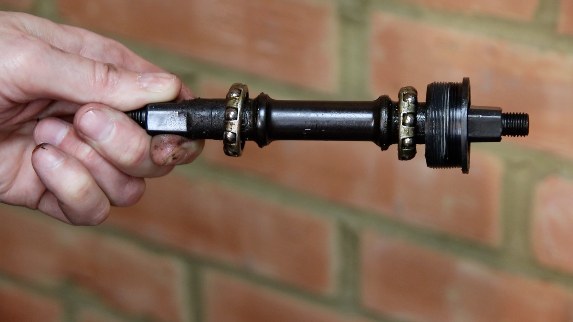
66) You can now extract the crank axle, carefully ensuring you extract both bearings with the axle

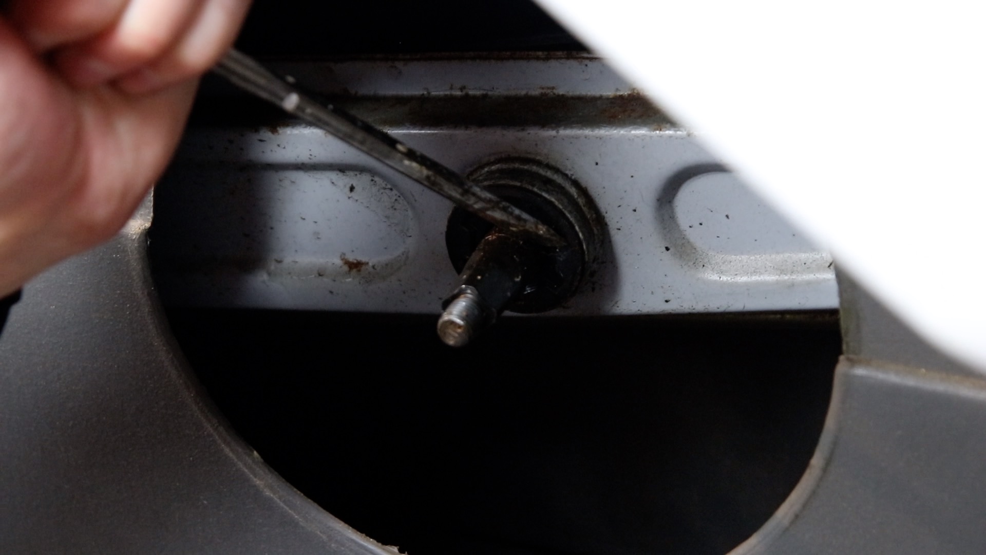
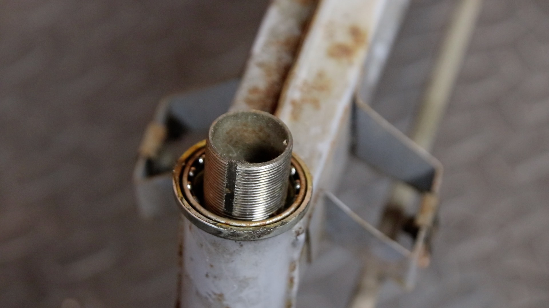
67) Looking into the chassis to inspect the threads

68) Inspecting the crank axle with bearings
69) Remove four M6 (25mm) bolts and mudguard washers that fix the canopy to the chassis

70) Remove the front wheel cover. This just pulls apart
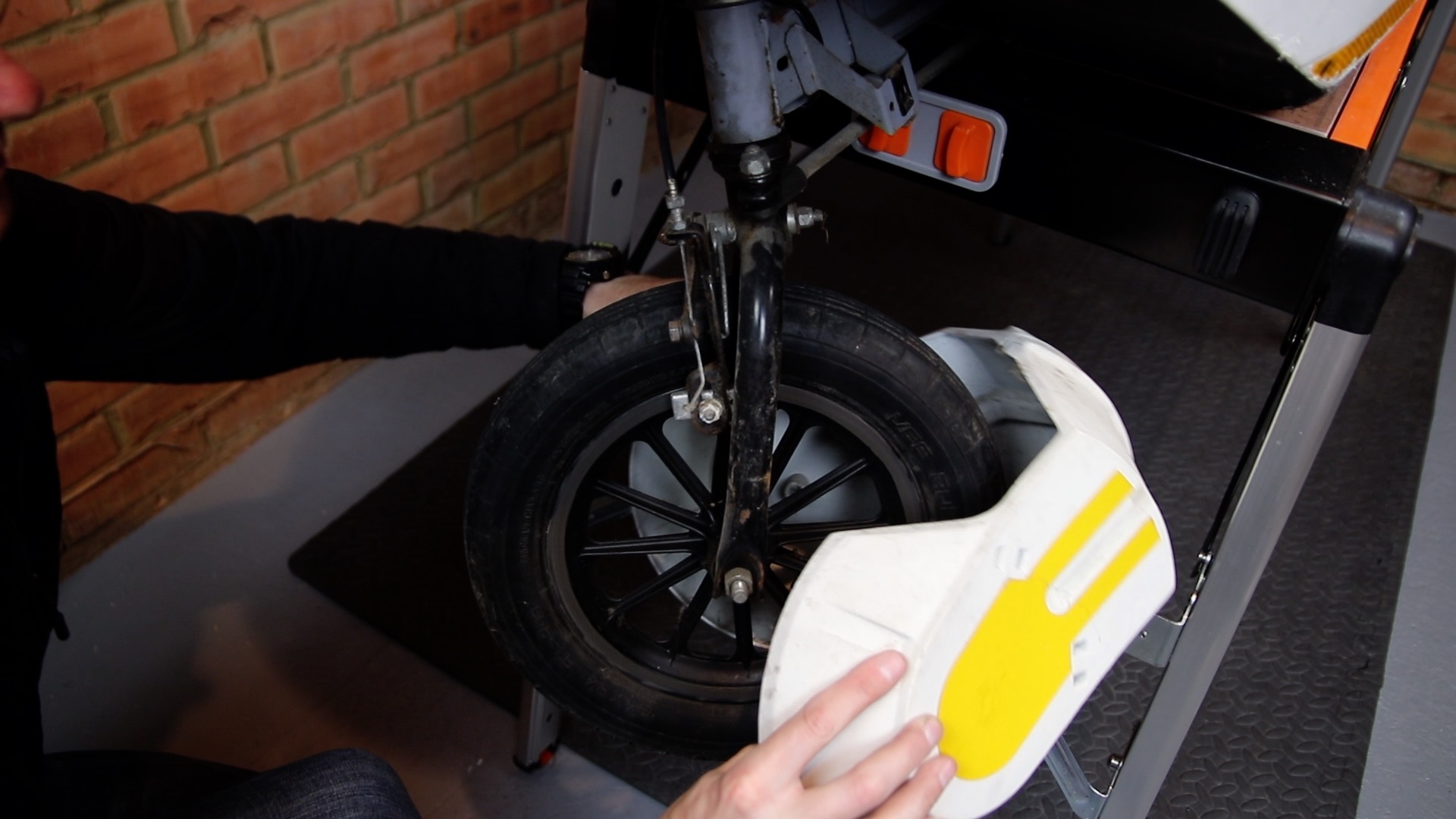
71) Slacken the nut on the front brake cable so you can remove the brake cable

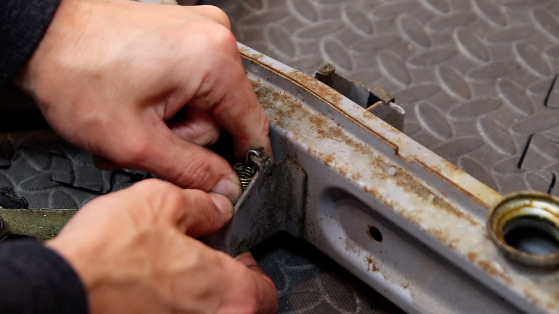
72) If the C5 is on a workbench, as shown in these photos, when you remove the canopy the chassis will fall onto the workbench. This will mean that the chain tensioner is smashed against the workbench.
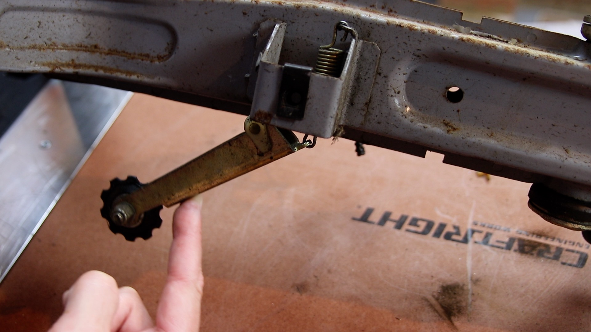
To prevent this, remove the chain tensioner first (although this may be tricky with the canopy in the way). You should at least disengage the tensioner from the chassis by pulling the metal part downwards. Leave the spring until later. If you remove the canopy with the C5 on the floor, you won’t have this problem.
Here we see the tensioner in place:
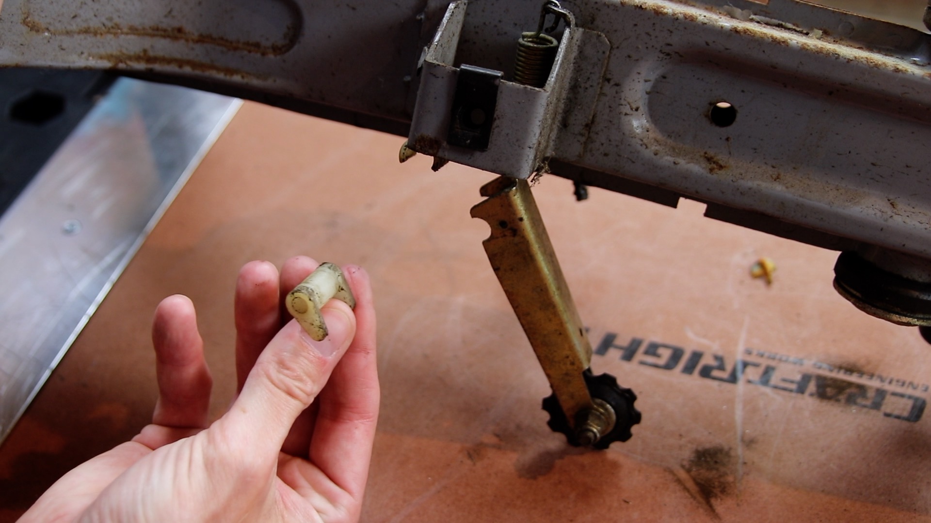
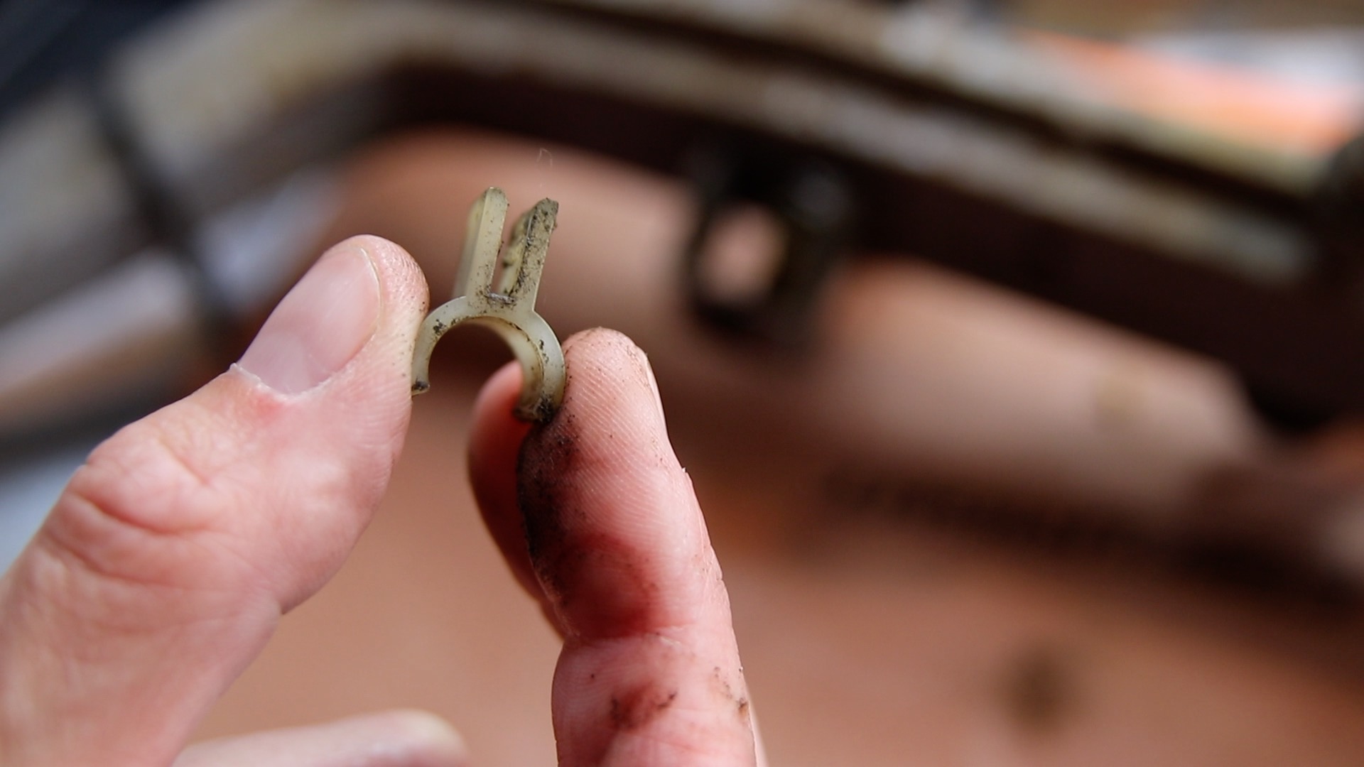
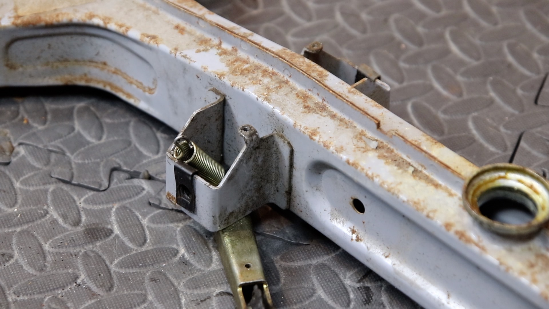
And here with the tensioner disengaged by pulling downwards. Collect and store the two small plastic parts:
73) Check that no cable ties or brake cables are snagged on the canopy, before lifting it away from the chassis

74) The chassis and front wheel are revealed

75) Place the C5 on the floor
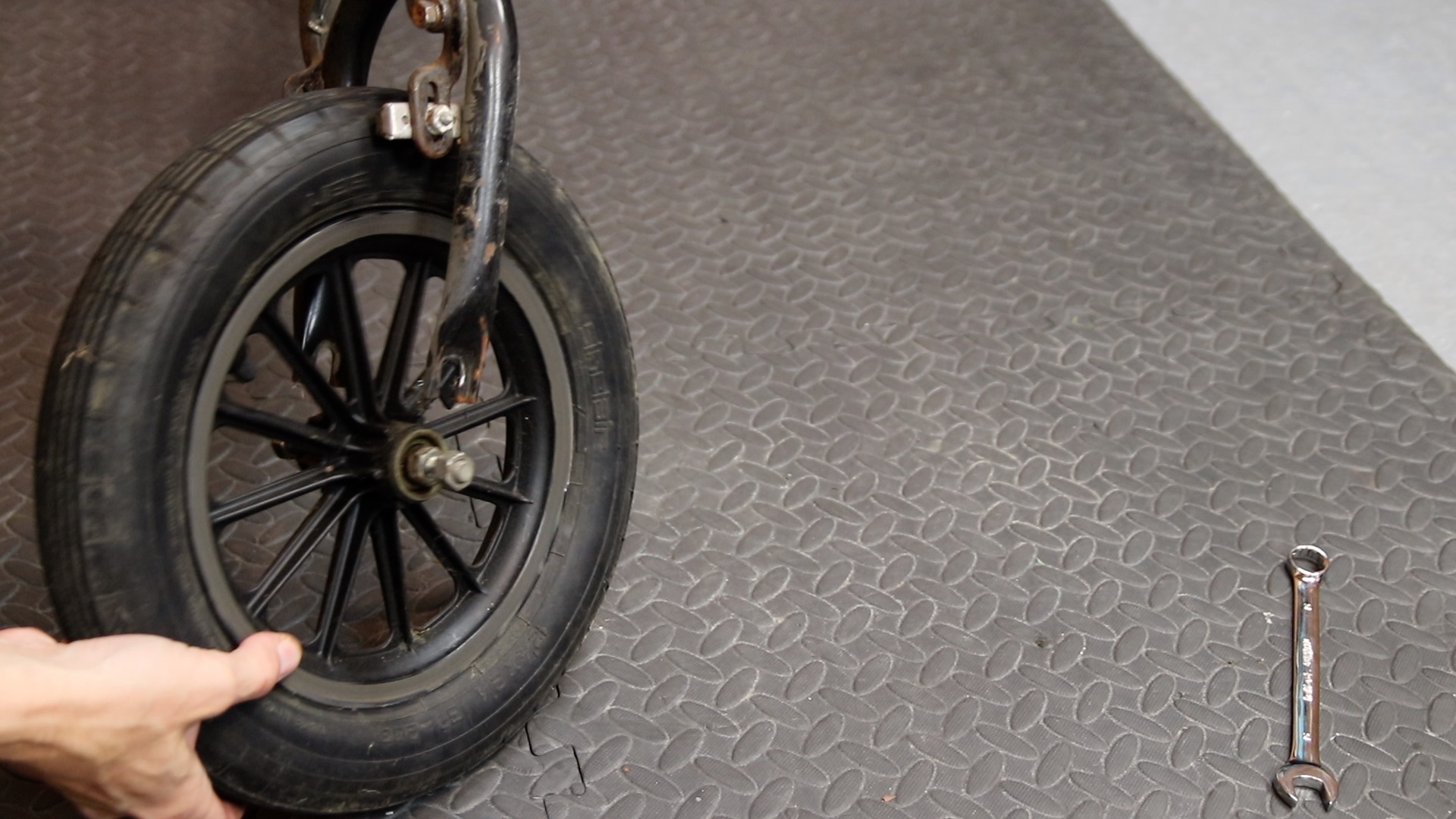
76) Slacken the two nuts either side of the front wheel, then remove the wheel
77) Remove the nut at the rear of the brake calliper, then remove the calliper assembly

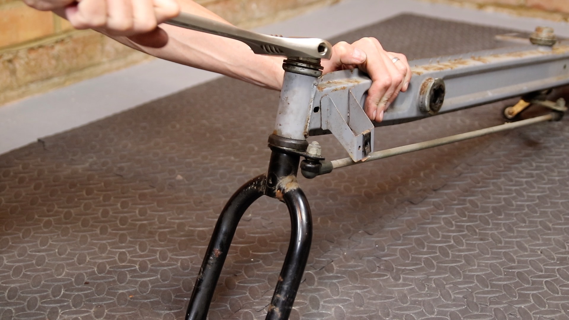
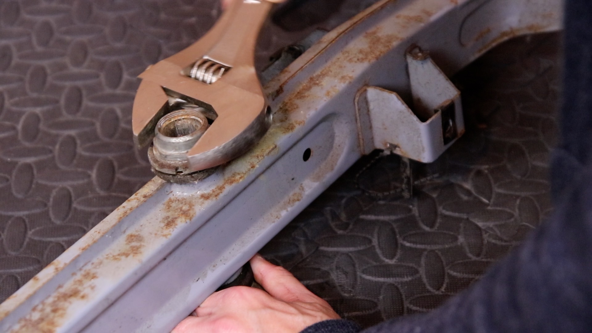
78) Using a very large spanner, remove the top nut
79) Remove the notched washer

80) Remove the bottom nut
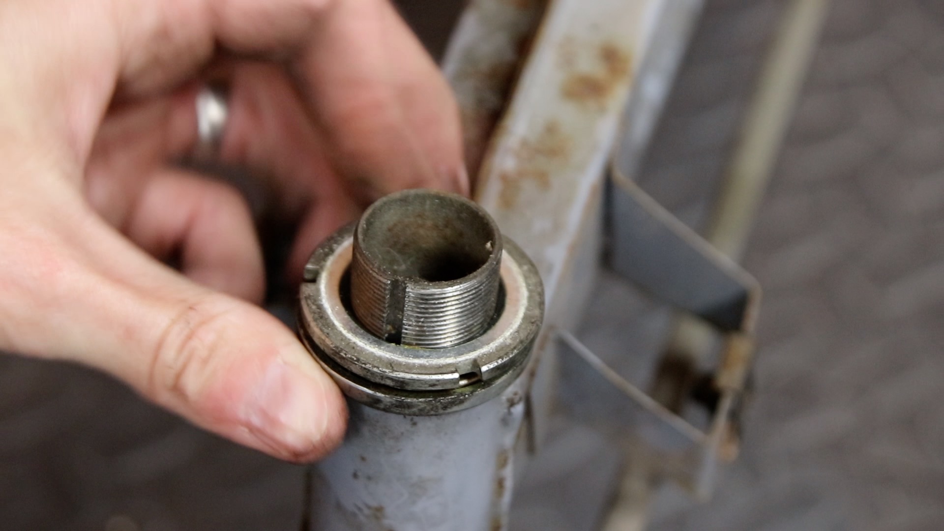
81) This will reveal a bearing
82) With one hand on the chassis, and the other on the forks, lower the forks
83) Tilt the bottom of the forks forwards, to disengage the steering bar

84) Note the bearing from the bottom of the chassis will likely drop out. Be sure to collect both bearings

85) Here we see the chassis with stearing bar
86) Remove the top but from the centre of the chassis
87) Remove the notched washer
88) Remove the lower nut

89) Note the bearings and remove them
90) Remove the lower steering column from the chassis, and disengage the steering bar

91)Disengage the spring from the chassis that holds the chain tensioner
92) You can now remove the chain tensioner and spring
93) Remove the left side black nut, by knocking it anti-clockwise with a screwdriver and hammer (this has a right-hand thread)

94) Locate the four black captive nuts on the chassis
95) These can be removed using a medium flat blade screwdriver as shown, and sliding upwards
96) Remove the two black plastic strips from the chassis. These prevent wires getting chafed by the chassis
97) Remove the captive cable tie from the centre of the chassis
98) Remove the two captive plastic inserts into which the control box screws. Press the plastic together using large pliers, then pull out

99) The chassis is now completely stripped, ready to be sanded and painted. For best results, it can be handed to a local powder coating firm. It should be “bead blasted” then powder coated. Bungs will be required in the openings, and the cups will need masking off.
JORDAN8ISH
Is the video I made 10 years ago
Thanks Chas! Your video linked at the top of this page helped me to take the C5 apart – couldn’t have done it without you – so many thanks. Hopefully this page builds on your video and it can be printed out so you other C5 owners can follow it in the workshop.
Very nice illustrations. I know how time consuming it is to do such good documentation. I’m restoring one now. Powder coated the frame, converting to disc brakes, and will got a 24v LiFE battery with twist grip throttle and speed controller instead of all on/off.
Thanks Dave. Glad the information was useful. Dave
Dear Dave,
The brown connector to X5 in the Control box. where does this lead to?
Regards
Simon
X5 is the auxiliary 12V connection. This goes back to the battery (or the key switch on an original C5). It is a parallel feed of +12V from the battery that is fed to the lights and logic (rather than the beefier connection to the motor via the relay).