Introduction
In this final video showing the restoration of my C5, I take a look at the electrical side of the C5. Back in 1985 the Sinclair C5 was marketed as an Electric Vehicle, or EV as we’d call them today.
In this video I’ll take you on a tour of the vehicle electrics, service the motor, fit a “safety wiring loom” and make some modifications to the pod, which should make it less prone to damage by static electricity.
C5 Electrical System – Overview
The electrical system of the C5 is designed to give a visual status to the user of two key parameters: battery condition, and the current taken by the motor. It does this using two bar-graph displays in the pod. It also includes several protection features to prevent damage to components.
The left hand display is motor current. It has 5 leds – 2 green, 1 yellow and 2 red. If the display is green then the motor is operating within its safe continuous rating. If yellow or red are showing the motor is overloaded and the user should assist by peddling. The motor temperature will be increasing and it will eventually be disconnected after an audible warning is sounded, to prevent burnout.
When high currents are drawn, and motor overheating can be rapid, the system cuts out after an appropriate time and remains locked out until battery power is removed and then reconnected. This form of protection can detect a deliberate stall within a few seconds.
The right hand display is a form of fuel gauge. The bar decreases in length as the battery is discharged. Warnings are again provided before disconnection.
To maximise operational range and prevent transmission strain, the C5 should always be got underway using the pedals.
Tour of the C5 Electrics
I made a test rig, or as I like to call it, a Sinclair C5 Simulator, in order to demonstrate the vehicle electrics. This comprises a wooden board with all the electrical parts laid out, including an original wiring loom (kindly sent from the Netherlands by Kristof Poppe).
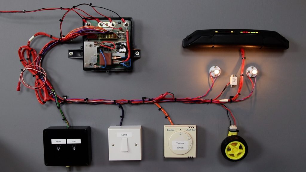
Here we can see the following components:
Control Box
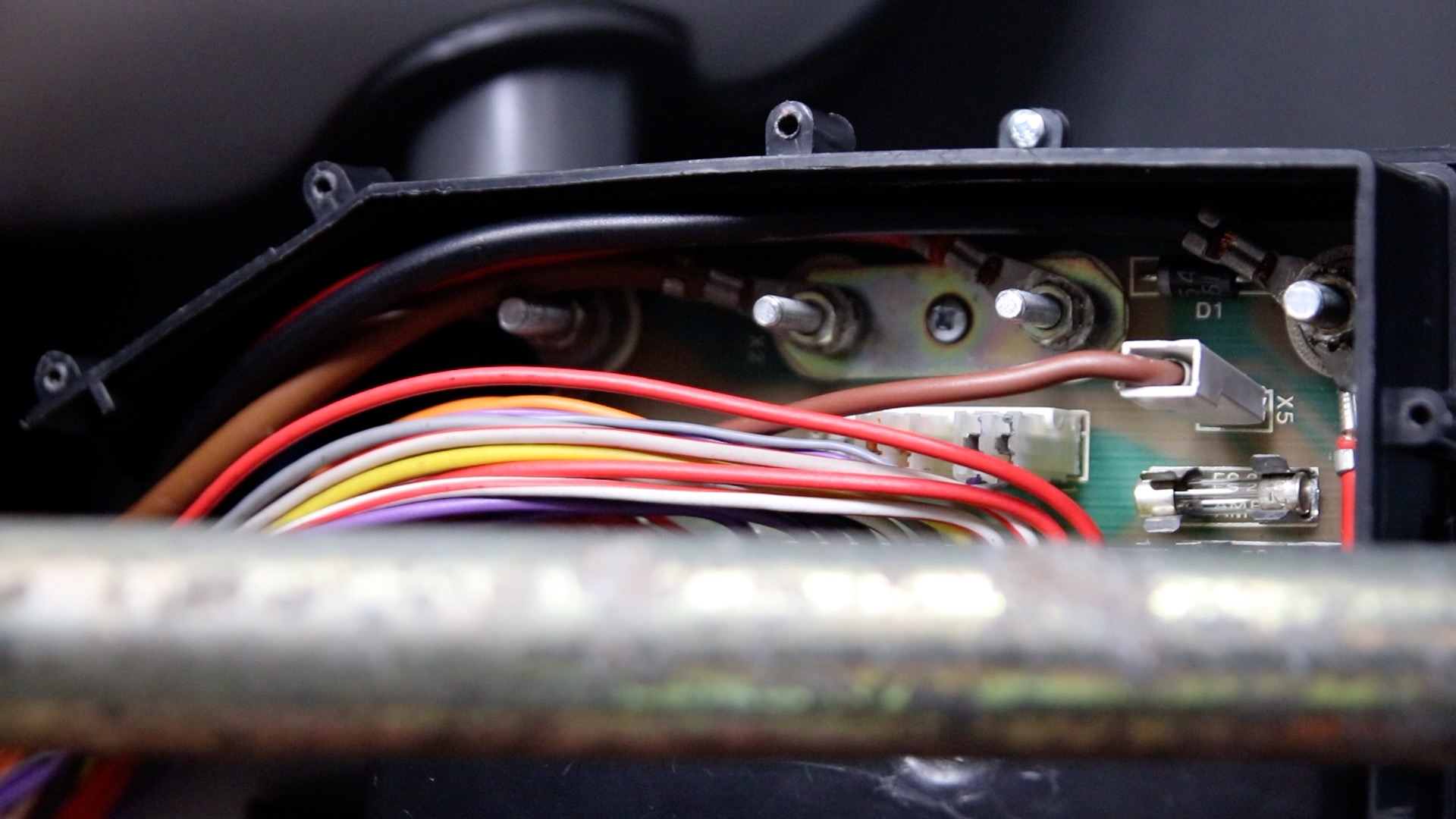
This is mounted in the rear of the C5 and acts as an electrical junction box. Here we can see the Control Box with the top covers removed:

It contains:
- Automotive relay (70 amp rating): This is used to switch the battery to the motor using a low current control circuit. The battery and motor circuit use very thick gauge wire as normal current consumption is around 30 amps. It has to be able to cope with higher current for shorter durations. The highest current expected is 140 amps for up to 4 seconds. The current varies considerably depending on the gradient you are driving on. The worst case is when you are standing still, and try and start the C5. If the motor is powered, but not moving, this is called the stall condition. For this reason, you are supposed to get the C5 moving using pedal power to avoid this very high current state. A relay coil should have a diode connected across it (in reverse polarity) to help dissipate the charge that is stored in the coil, at switch off. This is called a freewheeling diode, and a check should be made that it is not blown (see later).
- Shunt: This is the steel plate that enables us to take a “sniff” of the current used in the motor circuit. This is in effect a 0.001 ohm resistor (but capable of carrying a very high current). This enables us to keep track of the motor current in the left hand pod display and provide lock out, in case of a motor stall.
- Op Amp: This is a small 8-pin IC, that contains two op amps (amplifiers). One is used to condition the current “sniff” signal from the shunt. This is is now a voltage that is proportional to the current. The signal is passed to the pod, where it goes into the ULA chip so that the current value can be displayed in the left hand bar graph. Another amplifier in the control box also conditions the current sniff signal. This is then passed to a couple of transistors which create a lock out signal, which prevents the relay turning on, should the motor current exceed 140amps for more than 4 seconds (motor stall).
- Fuses: There are two fuses. The “auxiliary” 12V feed from the battery comes in on the brown wire to connector X5 (the wire is red in my test rig above). This then passes through two fuses F1 and F2. F2 (1 amp, fast blow, 25mm fuse) is the top fuse. This provides a fused circuit to supply the vehicle electronics in the pod and control box. F1 (5 amp, fast blow, 25mm) supplies a circuit that powers the front and rear lights, as well as the horn and indicators (if fitted). Note the motor circuit (fed by the separate thick wires) does not have a fuse.
- Regulator: A 5 volt regulator steps down the 12V from the battery to 5V which is fed to some of the other circuitry.
- Commutator diode (aka. flyback diode): This is the diode top right, and is connected in reverse across the motor. Current does not flow through the diode when the motor is powered.
The motor acts as a large inductor. When the motor is turned off, the relay contacts open which isolates the motor and the inductor contains a store of energy. In order to provide a path for this to energy to dissipate, a diode is connected across the motor. Current flows through the diode and back to the motor in a loop, and the energy decays. At this time the current is large but only flows for a very short time, which the diode can cope with (peak surge current). Without this diode, when the relay is turned off, a very large voltage appears across the relay contacts. This may arc and cause the relay contacts to weld together (and therefore the motor carries on running), or damage the relay contacts.
It is very common for this diode to blow on a C5 for the following reason:
When you push the C5 backwards, the motor acts as a generator. The only things in circuit at this time are the motor and the diode. Therefore a continuous current will flow through the diode. The diode is only rated at 3 Amps continuous current, and this is easily exceeded and the diode is damaged.
If the diode has blown, this will cause damage to the relay contacts for reasons explained above. A check should therefore be made of the diode, with a multimeter.
Multimeters have a “diode check” mode. With the C5 powered off, You should see the diode conduct in only one direction, and the voltage drop is shown (e.g. 0.5V):

To check the commutator diode, you need to unsolder the diode (or disconnect the motor).
My commutator diode had blown, and was showing “0V” on the multimeter in both directions.
The documentation shows this is normally a 1N5401 diode. I found a 1N5404 in its place. However, both devices have similar ratings for continuous forward current (3A) and instantaneous peak current (200Amps) and are both suitable.
The Pod
This is the small black box that sits in front of the driver. It contains the Head Up Display which comprises two bar graphs. The function of these is described in the overview section above.
It is noteworthy that the right-hand display does not show the battery voltage directly. This would not be a good indication of the charge state of the battery is it does vary under load. It should be thought of as a fuel gauge.
The pod contains a circuit board and a microchip called the ULA. This is discussed in more detail in a later section, when I make some modifications to the Pod.
Motor
This is a specially designed DC motor. It is rated at 12 Volts / 300 Watts. Some users modify the C5 to use 24 Volts which improves the hill climbing ability of the C5, but increases the heat build up.
On my C5 simulator, the motor is replaced by a small yellow model motor.
Lights
There is a front and rear lamp. Originally these were tungsten lamps. These may be replaced by modern LED equivalents. The lamp holders / diffusers command high prices on eBay.
Controls / Switches
There is a microswitch under the left hand-grip on the handle bar. This activates the motor (subject to inhibit from the control box / pod protection circuitry).
An optional extra was to have a second microswitch located under the right hand-grip. This activated a horn (a small buzzer).
On my simulator the switches are mounted in a black box.
Thermostat
The C5 has two forms of thermal protection:
- Thermistor: This sits in a tube inside the motor and has purple wires. Should the motor get too hot, a buzzer will sound. If the temperature continues to rise, the motor will cut out. On my simulator, this is replaced by a knob on the black box, connected to a variable resistor (potentiometer).
- Bi-metalic strip: As a fail-safe, there is a bi-metallic strip (temperature controlled switch) that is clipped to the metalwork on the outside of the motor. This has orange wires. If the motor gets too hot, the switch will open and this will stop the motor. In my simulator, this is shown by the household thermostat (this also contains a bimetallic switch).
You will see that Sinclair Vehicles went to some lengths to prevent the motor overheating. This is important as the laminations could melt if it got too hot, and the motor would be destroyed.
Electrical modifications and servicing
The rest of this page discusses servicing and repairs to the electrical system.
Safety Wiring Loom
Originally, the C5 came with a specially made lead-acid battery which was fitted with a special cap:
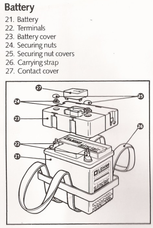
This cap had a switch assembly that was used to turn the C5 on using a key. There was also a button that could be used to turn the power off:
My C5 didn’t come with the above device, as a car battery had been fitted and the cabling modified with normal battery terminal connectors. These required a spanner to be used to connect the cables to the battery:

There are a number of flaws with the current set up:
- You need to use a spanner to connect / disconnect the battery for charging, or to turn the C5 off completely.
- There is a chance the battery terminals could be connected the wrong way around. This would lead to failure of the pod or control box electronics.
- The original switch had a cut out button. This was an important safety feature. The relay in the control box passes a very high current. It is possible that due to commutator diode failure (or some other reason), that the relay contacts weld together. This means the motor is permanently activated. In this case, you’ve got a “runaway C5” and no way of stopping.
I therefore fitted a “Safety wiring loom” which solves the above issues. It comprises a cable set that runs from the battery area to the control box. It also has a switch that replaces the light switch, and enables you to turn the C5 on and off along with the lights. It has a diode and a relay, which means that if you get the power connections the wrong way around, the power won’t be connected to the C5 electronics. Additionally there are quick-release connectors for the battery, so that it may be easily disconnected for charging.
I bought mine from c5alive.co.uk a few years back. I’m not sure if they still sell them, but eBay seller teresa1049 sells a similar kit. This seller is well regarded as a supplier of C5 parts.
I traced out the wiring of the loom and the circuit diagram is as follows:

I believe there is a flaw with the above loom from c5alive. If you connect the battery the wrong way around AND switch the three-position switch to the “C5 only” position, the relay is energised and power connected to the C5 electronics. This is contrary to the claim that the loom prevents damage due to getting the battery terminals the wrong way around. I contacted the seller about this concern, but did not receive a response. I am not too concerned as the battery connectors are coloured and I am careful to connect it the right way around. One day I will correct this limitation, which should just involve moving the position of the diode in the circuit.
Here are the steps to fit the safety wiring loom. Note that as these looms vary you should follow the instructions provided. This may differ that those shown below.
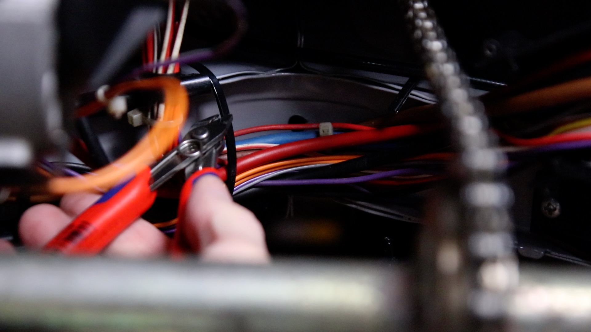
1. Remove the control box lid and disconnect the brown wire from connector X5 – this just pulls off. Use a spanner to remove the thick cables from the top left terminals (these come from the battery and are usually blue and brown):
2. Cut cable ties to allow removal of the wires:
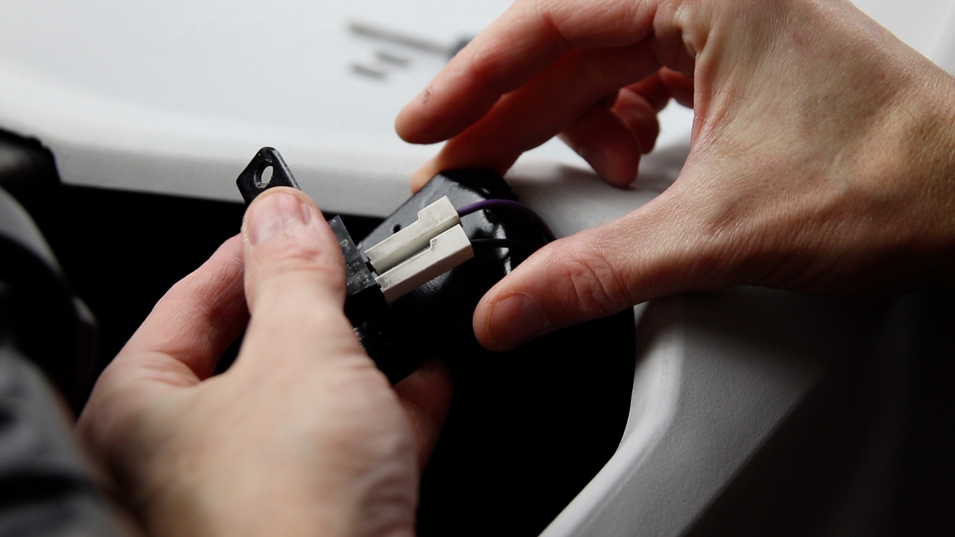
3. Unscrew the light switch bracket, and then remove the two connectors. They just pull off:
You should now be able to completely remove the old wiring loom.
4. The thin black wire that was removed from the switch is no longer needed (this is an unswitched 0V feed from the control box). It should be careful cable tied out of the way in the boot area:

5. Push out the old switch (press in the two tabs on the side), then slot in the new switch. This switch has a diode soldered to it. Then connect the two wires from the wiring loom to the switch. These were connected like this when I was sent the loom. I marked the wires as you can see here (M for middle and R for right). One of these is OV from the battery, and the other feeds the relay in the wiring loom.

6. Connect the purple wire that was removed earlier. This is the switched 0V that feeds the front and rear lights:

7. Drill a small 4mm hole to the top right of the hole that connects the footwell to the boot area. Mount the relay here using a nut, bolt and shake proof washer. Then refit the switch bracket.
8. Feed the new loom through the grommet into the boot area:

9. Attach the wires to the control box. The black wire (this is now the switched 0V from the battery) connects to the top left terminal. Next is the red wire (+12V). Lastly, the brown wire connects to X5 using a push on spade connector. This is a second feed of +12V from the battery and is known as “auxiliary power“. This feeds the electronics (not the motor):

10. Tidy up the wires using some cable ties:

11. Install a car battery, or better still, a leisure battery. This is more suited to the deep discharge cycles the battery will experience in this application:

The 70AH unit seen here is from Halfords and is model HLB678 which fits the space nicely. You should also fit a strap to ensure the battery does not slide around when you are in transit. The C5 has mounting positions for a strap, but you may need to modify this as this battery is larger than the original Sinclair battery. This battery has around double the capacity of the original Sinclair (Oldham brand) battery.
After some use though, I decided this 70AH Halfords battery is just too big. It is difficult to strap it into the C5 and is very heavy. If you are looking for battery I would recommend the following:
- LiFePO4 (Lithium) battery (price around £180 including mains charger as 2024). The recommended unit that can cope with the high current from the C5 is the following (price around £180 including mains charger as 2024) is an Ultramax branded 36AH battery (model SLAUMXLI36-12). I bought one in 2023 from batterymasters.co.uk and it works very well. With a lithium battery, the voltage (and therefore speed) are maintained throughout the discharge cycle.
- Bog standard car battery (Halfords do a 41AH car battery for £65, as 2024): Although it is not recommended to deep discharge these types of battery, it has been found they work very well, they are not too large (unlike my leisure battery) and you can just buy another one if it stops holding its charge. I should have bought one of these instead of my leisure battery in hindsight.
Battery Care
Lead acid batteries should be kept topped up with charge where possible. This includes during periods where the battery is not in use (e.g. over winter). This means charging it up every month or two.
A car battery is used to having a high current drawn for a short period when the car is first turned on. It is then charged up immediately using the alternator. You can see that this is very different from the use it experiences in a C5. In this case the battery is discharged until it is drained. Infact, there is usually a point at which you should not drain a battery any more without damaging it.
Note that battery voltage gives you a good indication of maximum charge state, and minimum charge state – when it is being charged up. However, under load, the voltage will drop and the pod compensates for battery voltage before showing it on the LED indicators (right-hand display). It also contains a circuit to cut off the motor (“lock out”) when it detects the battery charge is low. The right-hand pod bar graph is not a volt meter.
A leisure battery has a different construction to a car battery and is designed to suffer higher discharge. For this reason it is better suited to powering the C5.
One common modern upgrade for C5’s is to fit LiPo (Lithium Polymer) batteries. These are light weight and offer long running times.
For more details on battery care, take a look at the following web page.
Servicing the Motor
If a C5 hasn’t been used for many years, the motor has likely seized. The carbon brushes may be stuck to the commutator. In this case you can squirt a some WD40 in the rear of the motor housing to help free them up. However, it is a good idea to dismantle and service the motor at the first opporunity. The grease in the motor goes hard over time, and the carbon brushes shed fine dust through use.
Paul Grice has some excellent Sinclair C5 tutorials on YouTube. Using these as a guide, I was able to service the motor.
The motor was specially made for the Sinclair C5 by an Italian company called Polymotor. The UK press spread an unhelpful rumour that the C5 used a washing machine motor. This was not the case and likely came about as the vehicle was assembled by Hoover who also made white goods. In addition, Polymotor made washing machine motors. However, they also made motors for torpedos and other high tech applications.
In order to remove the motor from the vehicle, consult the tear down guide (part 2 of the video, and there is a full write-up on this site).

- The first step is to identify what type of motor you have. Early motors had brown plastic on the “fingers“:

(Photo courtesy Edward Green)
This plastic was brittle and if you have this version, you should not attempt to dismantle the motor as described in this guide. If you do, the plastic fingers will likely break off. Instead, you should remove the rear of the motor and clean as best you can.
If you have cream fingers as shown below, you may proceed.
2. Insert a match stick in-between each of the plastic fingers:

Repeat for all the fingers:

3. This should have dis-engaged the catches from the fingers, which allows you to gently tap the brown plastic catches using a large flat-blade screwdriver.

4. This will push the brown gearbox housing off the motor:

5. Now pull out the gears:

On the bottom are three planetary gears, so called as they orbit the central gear. Check them for damage.
The front pinion is prone to wear and should be checked:

Excessive wear on this pinion is likely caused by the motor tilting during use. This effect can be minimised using a metal bracket (fitted to later C5’s including mine) or using cable ties (see video 3 at 12’41”).
Note that there are two metal bearings on the end of the motor shaft in the above photo. Sometimes one of these can break off. Also note the condition on the pinion that we can see behind the two bearings.
6. Remove the rubber gasket for safe keeping:

7. Rotate the motor shaft. It should be free to turn. If it does not turn or is very stiff, don’t worry as we will soon get inside and try and improve matters:

8. Make a mark on both the fingers and the metal motor housing. This will allow you to get the correct orientation when you re-assemble the motor:

9. Pull the brushes away from the commutator and hold them in place. This can be acheived by pulling the copper braid using a screwdriver. The brushes are spring loaded. They are also prevented from coming completely out (don’t pull too hard). Jam in a couple of screwdrivers against the motor case so that the brushes stay pulled out:

10. Remove the two long bolts:

11. Hold the middle of the motor body, and work the work it away from the end cap (the rear metal part of the body):

12. Inside the end cap you should see two washers. They were missing on my motor:

There should be one crinkle washer (in the rear) and one flat washer as you can see in this photo:

13. Release the brushes and inspect them. They should be slightly curved, and not have any damage. They should also have some travel against the spring to indicate they have not worn down too far.
14. Inspect the end of the now exposed motor. The end bearing should turn freely:

Also inspect the commutator (the blackened copper section to the left of the bearing in the above photo). This makes contact with the carbon brushes which wear and cause the copper to blacken. This should be free from pits or damage.
15. Push the armature out of the motor housing. This is quite difficult as there is a strong magnet inside the motor housing:

16. Looking inside the motor housing, we can see the stator. This is a stationary permanent magnet. The magnet is very strong:

17. Remove the commutator from the plastic sleeve. This should just require a gentle waggle and pull:

18. Here we can see the armature on the workbench:

This part comprises an iron core wound with a number of copper coils. Each coil is connected to a pair of contacts on the commutator. When a coil receives power via the carbon brushes, a magnetic field is produced. This interacts with the field in the permanent magnet (in the stator) and the shaft rotates. This causes the commutator to connect up another pair of contacts, along with another coil. The process repeats and we have motion!
In the photo above you can see that there are some horizontal score marks on the iron cores in the armature. These are to trim the weight of the core. This was done when the motor was manufactured to try and keep the centre of gravity along the centre axis.
19. Clean inside the motor housing. This is likely full of black dust from the normal wear on the carbon brushes:

20. Clean off the old grease from the gears and gearbox housing using a toothbrush and some white spirit:

21. Clean the commutator gently using some fine grit paper to remove the carbon:

22. Then wipe with a cloth and some white spirit. You should see a bright copper surface on the commutator:

23. We can now start the re-assembly process. Start by locating the two washers for the end cap.
One is crinkled and this goes in the end cap first:

Then insert the flat washer on top of the crinkle washer.
24. Insert the armature into the motor housing. There is a strong magnet in the housing and the two parts will repel initially. I found a swift and confident plunge to be a good technique to get the armature in place:

Once the armature is centred in the housing, it will stick to the side of the housing by magnetism.
25. Make sure the brushes are still retracted. Now insert the motor body into the end cap. There is a notch in the side of the motor housing that needs to like up with the end cap:

26. Align the marks that were made on the plastic sleeve earlier, and the motor housing, and slide the sleeve on:

27. Insert the two long bolts and tighten them up:

28. Lubricate the bearings in the brown gearbox housing using a few drops of oil:

Rotate the bearing to work in the oil:

29. Apply some lithium based grease: firstly to the shafts that house the three planetary gears:

30. Insert the gears into the gearbox housing:

31. Apply some grease to the gears and rotate the assembly:

32. Apply grease to the pinion on the end of the motor shaft. Also a few drops of oil on the bearings:

33. Fit the rubber gasket:

34. Fit the gearbox onto the motor housing. Gently tap it on with a rubber mallet so that you hear the fingers click into place against the catches:

35. Rotate the pinion in both directions. It should move slowly but freely:

36. The motor is now fully serviced and ready to go back on the C5. For instructions on fitting the motor to the C5, you’ll have to reverse the process detailed in my tear down instructions here – start at number 22. In order to set the belt tension, see part 3 of the series (13’18”).
Don’t forget to insert the thermistor into the motor once fitted. This needs to be held in place using heatshrink. The thermistor is inserted into the motor armature and keeps track of the temperature inside the motor. Should the motor overheat, the control circuitry kills power to the motor to prevent damage.

Pod Clean-up and Reliability Modifications
The pod is a small black box that clips under the canopy:

It contains two LED bar graphics that perform various functions, as described earlier. These bar graphs form the “head up display” as it is referred to in the Sinclair C5 owners handbook. At the rear is a single 0.1 inch pitch connector. A red cable connects to the Control Box in the rear of the vehicle.

Inside the pod there are a few components and an IC called a ULA (uncommitted logic array). This was an early type of customisable chip, that contained both digital and analogue components. These components formed a toolkit for designers to connect together using a single metal layer. This method of creating custom chips was far cheaper than creating a design in silicon. The device was made by Ferranti, and was likely chosen by Sinclair due to their use in their computers such as the Sinclair Spectrum 48k.
The device is susceptible to damage from static and spurious signals on the input lines from the vehicle. Once it is broken – that’s it for your pod unless you can get another ULA of the same type.

More recently, a ULA replacement has been developed. This is a small PCB that sits in place of the ULA. It isn’t exactly the same, and the Control Box also requires a small modification to work with this device. Full details of this open source project can be found here. From time to time, folk on the Sinclair C5 Owners Facebook forum create a batch of these devices for sale.
As the ULA is static sensitive, I suggest the use of an anti-static wrist strap when working on the pod:

One of the faults I’ve seen with my C5 since I bought it was intermittent motor cut out. This could be solved by waggling the red cable at the rear of the pod. This is a common issue and is caused by corrosion of the contacts in the connector:

You can replace this connector, otherwise clean the contacts with a fibreglass pencil as I did. This removes any oxidised material. You should also squirt some contact cleaner or WD40 into the socket on the red cable, and plug/unplug the connector a number of times before the solvent evaporates. This should clean the contacts inside the socket.
The ULA is socketed. The contacts on the IC pins, as well as the socket may also become tarnished over time. I therefore carefully removed the ULA and cleaned the legs with a fibreglass pencil. Great care must be taken when removing the ULA. I have a cheap chip puller, but as the IC was stuck fast it, I gently prised it up a few millimetres using a flat blade screwdriver. Be careful not to touch the small potentiometer next to the IC when you do this.

There are some modifications that can be made to the pod to reduce the ULA’s susceptibility to damage. These modifications are outlined in the Unofficial Sinclair C5 Service Manual. This manual was written by P. Milner and Perran Newman, who worked on the C5 project for Sinclair. Circuit diagrams can be downloaded from c5owners.com.
The first of these modifications involves inserting a resistor in-line with pin 3 of the ULA. This requires that you cut the track between the connector (X1) pin 6 and IC pin 3 as shown below:

Then solder a 47k resistor between IC pin 3 and connector pin 6. This should be insulated with heat shrink to stop its leads shorting against other components:

The second modification is to install catch diodes on one of the ULA’s input lines (IC1 pin 4):

The idea is that these diodes prevent large signals from entering the IC from the signal line. Normal signals will not cause either diode to conduct, and the signal passes to the IC input as normal. If there are nasty spikes on the signal greater than +5.5V (the + supply voltage + diode drop), the upper diode conducts and the signal is spirited away to the positive voltage rail rather than into the IC. If a signal less than -0.5V is present on the signal line (0V rail – 0.5V diode drop), the lower diode conducts and prevents the signal from going into the IC input. These diodes can be said to catch unwanted high voltage signals (what we may call static). This is a common method of protection of inputs on devices. Any small signal diode will do, and the unofficial service manual suggests using 1N914 diodes. This is an old type of diode, and a modern replacement is 1N4148.
This is quite fiddly and care and good soldering skills are required. I would remove the ULA before soldering, to avoid any heat damage to the IC.
Here you can see the finished result, and once again I have insulated the leads of the diodes with heatshrink:

You can see that some of the wider copper areas of the circuit board look wrinkled. This is normal for this vintage of circuit board and it was always like this – it has not degraded over time.
As I write this, some 14 months after making the video, I believe that I made a mistake with the diodes. The Unofficial Service Manual is rather brief on the modification details:
“Connect catch diodes (IN914) to Vcc and GND on IC1/4”
I think this actually means connect diodes to IC1 pin 4 – not IC pins 1 and 4 as I interpreted it at the time. Anyway I’ve looked at the circuit diagram and I don’t think the diodes are needed on pin 1, as this is part of a resistor network. It makes most sense to protect the IC from nasties on the signal lines from elsewhere in the vehicle, and pin 3 (protected by the new resistor) and pin 4 (protected by catch diodes) makes perfect sense as these are indeed signal lines from the control box. I have since removed the diodes from IC pin 1.
Once cleaned and modified, the pod pushes back in place on the two prongs under the canopy. Sam Rowell noticed that there should be some (rubber?) washers between the pod and the canopy. This perhaps explains the rattle when I use the C5.
The Finished Result
With the C5 all back together again it was time to take it out for a test ride. Here in Milton Keynes there is a grid system of 60mph roads and over 140 roundabouts. This is no place for Sinclair C5. However, we have a network of cycle and pedestrian routes, separate from the roads, called the Redways. This is ideal for a C5, although the vehicle does struggle with the many ups and downs as the Redway goes under the roads. Here you need to engage pedal power to assist the motor.
As a finale to the video series, I took the C5 out for a 5k run around Milton Keynes, and did some filming with a drone to get some fancy aerial shots:

I’ve enjoyed this project immensely and it has taught me many new skills. I’m more at home with electrical than mechanical projects, and the C5 required a mix of the two. It is fair to say that my C5 was in reasonable shape before I started – not the wreck that some painstakingly restore. However, my C5 benefitted from a complete strip down and restoration. I found some missing parts along the way. Some were incorrectly fitted and others faulty. I am grateful to the help of the members of the Sinclair C5 Owners group on Facebook for advice and parts.
I’ve also established a new hobby in producing occasional YouTube videos, and accompanying write-ups on this website.
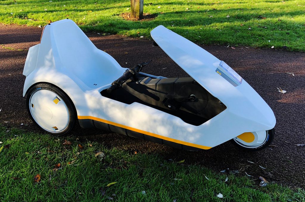
And below, the finished C5 looking good in the cool November light in 2018. Still futuristic, some 33 years after it rolled off the production line in Merthyr Tydfil.
Postscript
Since writing this article, I was contacted by Perran Newman, the designer of the C5 electrical system. He was employed by Sinclair Research and subcontracted to Sinclair Vehicles PLC.
We had good chat over Skype, and Perran discussed his time working on the C5 and working with Sir Clive Sinclair. He corrected a few details from this webpage and it has now been updated. Particularly my confusion around the generator action of the C5 when it is pushed in reverse. Perran has also contributed the overview section of this document.
I am grateful to Perran for getting in touch, and was pleased to see his enthusiasm for the C5 continues.