Background
I recently helped my neighbour clear out her loft. In amongst the old child’s toys and soggy papers we found a haul of retro goodies: An Amiga 1200, Sega Saturn and an original ZX Spectrum. There was also a large quantity of Atari ST games and accessories, which makes me think there is another machine hiding up there somewhere.
I dried out the items and tested and photographed them, as well as writing a description so my friend could list them for sale on eBay. She kindly gifted me the Amiga and the Spectrum. I decided it would be a nice gesture to restore the Spectrum and sell it to benefit a charity that had helped my neighbours family.
The Machine Condition
The machine was in a fair state on the outside. There were some sticky labels (Your Sinclair, a popular Spectrum magazine from back in the day) and the metal plate was pitted as happens with good use. Some of the legends on the keys had also rubbed off.

There are plenty of machines sold on eBay as “restored” when all they have done is replaced the capacitors and cleaned the front panel, but this Spectrum deserved a good deal more.
Restoration and Repair
Much of this restoration is a repeat of my previous video where I restored a pair of Spectrums. However, I have since bought a desoldering station which allowed me to go further with this machine as we will see. Here is the full list of improvements made to this machine:
- Replace capacitors (these can go bad over time and cause faults or degrade picture quality)
- Replace 5 Volt regulator (gets hot!) with an efficient DC to DC convertor (doesn’t get hot)
- Fit heatsink to ULA chip
- Composite video mod (replaces the noisy RF video output)
- Video transistor replacement (increases image contrast when used with the above mod)
- Repair any faults found (and there was a major fault discovered)
- Clean case
- Replace rubber key mat (the springy rubber part of the keyboard)
- Replace keyboard membrane (the electrical part of the keyboard)
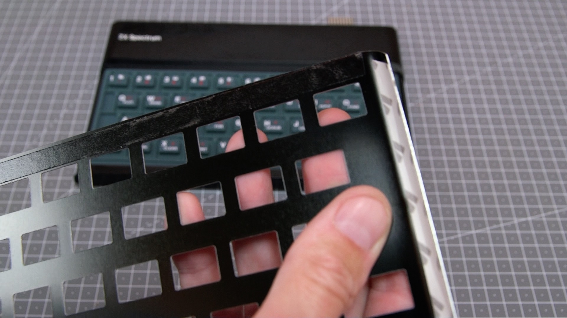
- Replace metal faceplate (surrounds the keyboard and has the alternative key legends printed on it)
- New rubber feet
As usual, I wore an anti-static wrist band thought the repair, to avoid damaging or reducing the lifespan of any ICs.
Pre-Power checks
As per the Unofficial Sinclair Spectrum repair manual (I can’t find this on the internet at the moment), and JoulesPerCoulomb video on YouTube, there are some checks required before you power up a Spectrum. These checks can highlight faults that if ignored, can cause further damage to the machine.
Here is a link to a webpage where someone has listed the checks from the JoulesPerColomb video which may be of use if you are having a go at this yourself.

The above checks suggest that there are no issues with the power supply or RAM. Issues with one can take out the other if power is applied. The lower RAM in the Spectrum has three voltage rails and is easily damaged if one rail is missing.
All these checks passed OK on this machine.
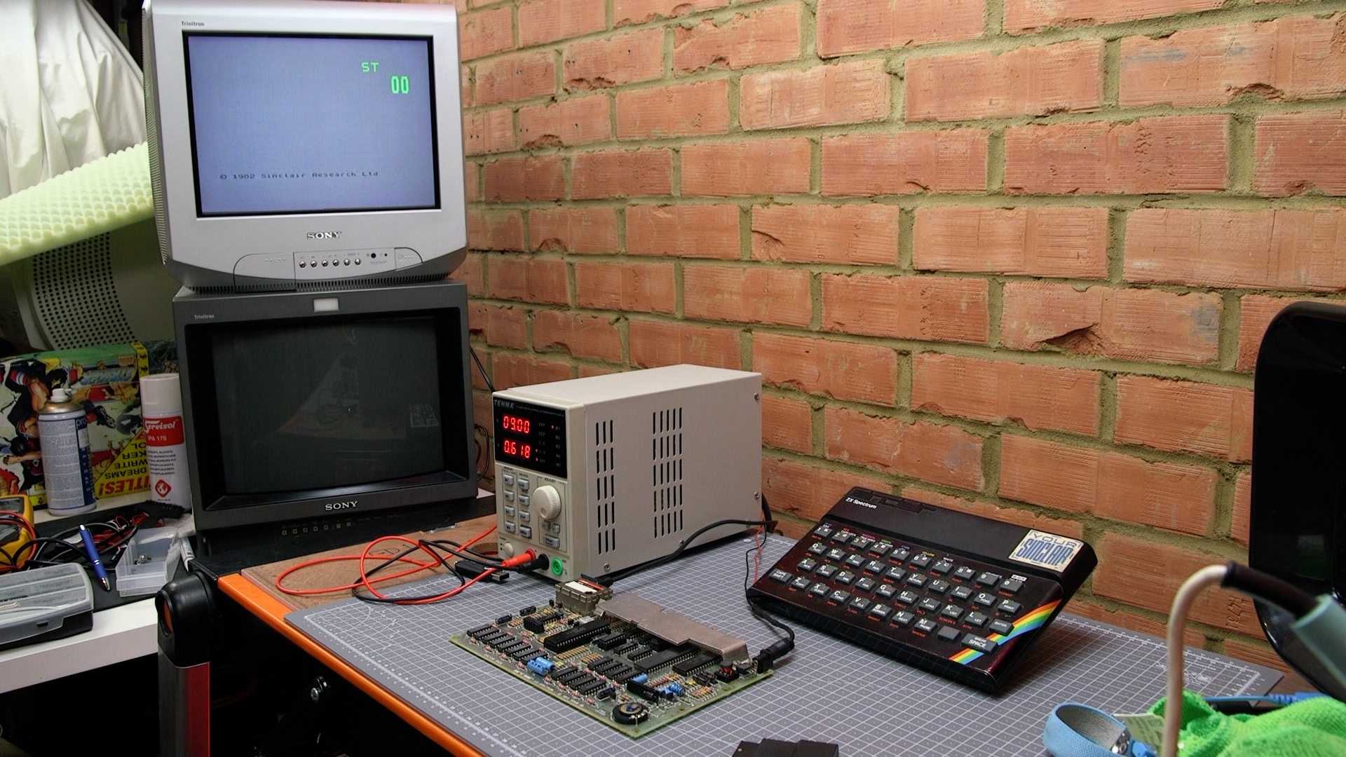
I now have a bench power supply which shows how much current is being drawn by the machine. It can also cut off the power if the current drawn is too high, which is a useful safety feature when repairing machines.
Diagnostic Checks and RAM fault
I used my SMART Card from Retroleum to perform some checks on the hardware. This device fits into the Spectrum’s expansion port and can boot into a ROM which checks out the RAM, the ROM, speaker, and allows you to check the keyboard.
Always be sure to add or remove accessories from the expansion port with the power turned off, otherwise you may damage the Spectrum.
The SMART Card immediately showed up a possible error with one of the RAM chips – IC21.

This fault was repeatable. This IC is part of the “upper RAM” – the upper 32KB.
The SMART Card has another menu for showing a visual display of the contents on the upper RAM.

In the above image, the SMART Card is writing 0’s to all upper RAM locations. It then reads it back and finds that there is a 1 in some locations, indicating a stuck bit (white lines).
In the Spectrum, there is one IC per bit of memory. So one byte of 00000000 has a zero stored in every memory location in each of the 8 RAM chips. A stuck bit in from one RAM chip will mean that every byte is read back as 10000000 (for example).
The photo above clearly shows that we have a stuck bit.
I therefore ordered a RAM IC from Retroleum. This was a TMS 4532-20NL3 device which was described as being suitable for all Spectrums. You have to be careful as some brands of memory are not interchangeable, and different types were used throughout the production run of the machine.
DC to DC Convertor mod
The original Spectrum was known to suffer heat build-up inside the case. In fact, one of the benefits of the later Spectrum Plus was a larger case with additional ventilation holes. Heat build-up will reduce the life of capacitors, which can then fail and take-out the power supply and/or memory. Excessive heat is also the enemy of ICs, so any reduction in heat production in the machine prolongs its life expectancy.
The Spectrum’s voltage regulator takes in the (approximately) 9V from the external power supply and creates a smooth 5V rail for the machine. However, it dumps a large amount of energy as heat in the large metal heat sink.

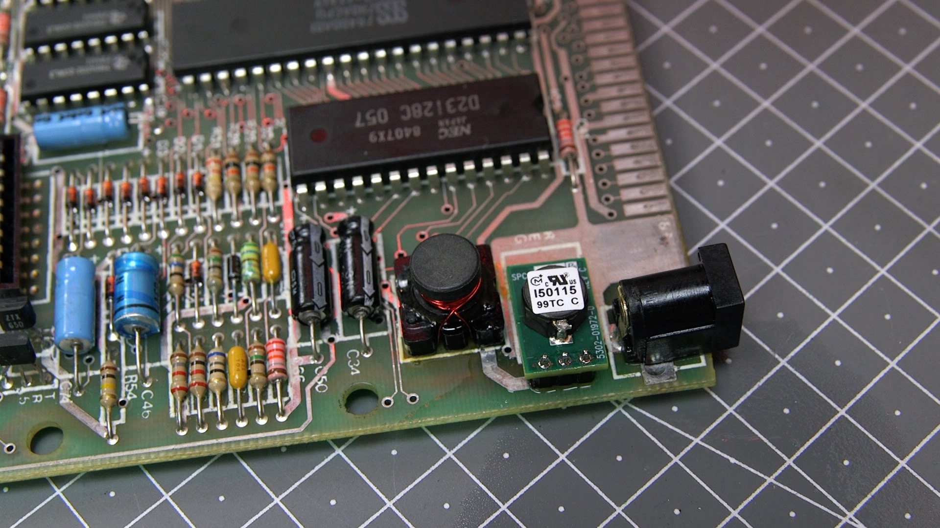
With this in mind I replaced the 5 Volt regulator with a more efficient switching convertor (DC to DC convertor). This is a like-for-like replacement and means that the metal heat sink is no longer required.
It is good practise to check modifications as you go along, ensuring you haven’t screwed anything up, before proceeding.
With the new convertor in place, there was a dramatic reduction in the current consumed by the computer to about 0.44 Amps. This illustrates how energy was being converted into heat.
ULA heatsink mod
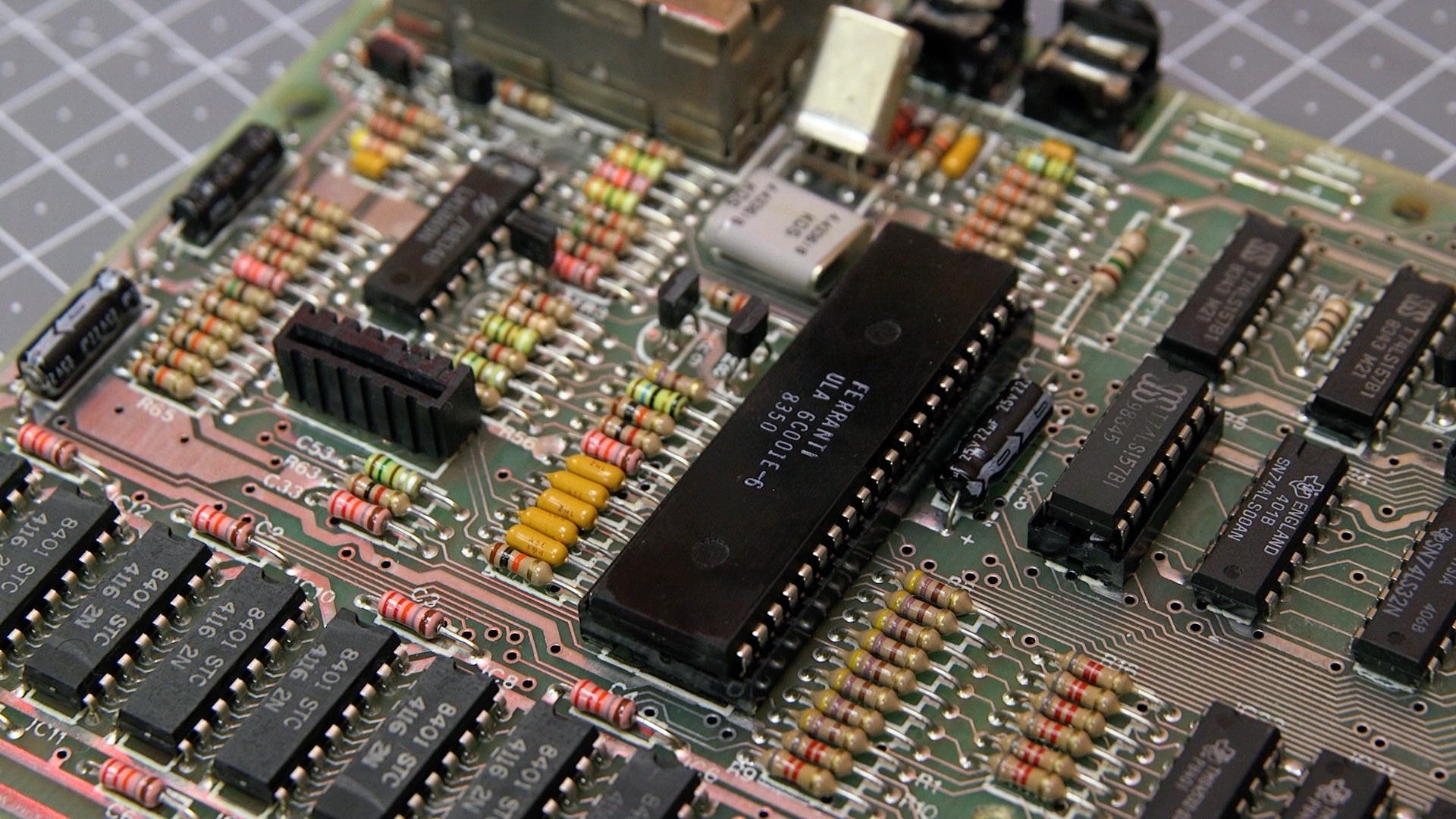
If the CPU is the brains of the machine, the ULA is the body. It is a custom chip that reads the keyboard, generates the display and controls the RAM. This machine has a later 6C variant. Even though this was a lower power version, it still gets quite warm. It is recommended therefore to fix a metal heatsink to better dissipate this energy and help prolong its life.
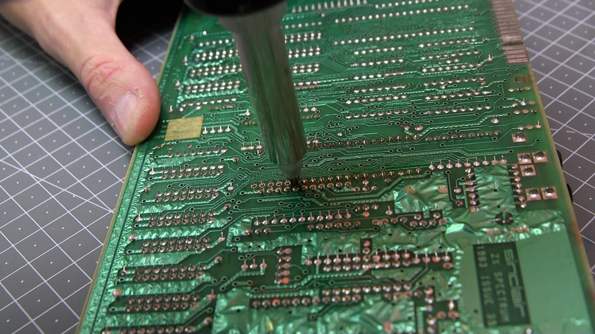
Unfortunately space is limited inside the Spectrum, so the socket in which the ULA sits must be removed in order to claw back some headroom for a heatsink.
Since my original Spectrum project, I have bought a cheap desoldering station. These are not a patch on the Weller desoldering stations I’ve used before at work, but they are 1/10th of the price, so in reach of the home user.
I have some experience with these tools and the key principles are:
- apply the desolder tool, hold it on for a second until the solder melts, rotate in a circular motion around the pin and only then engage the pump
- apply fresh solder and flux if you can’t get a hole clear
- don’t dwell too long on one pin – you can lift the pad (or damage an IC if fitted)
- patience is a virtue
This Duratool device blocks very easily so you are advised to clear out the chamber frequently (e.g. I did it every 20 pins).
I then soldered the ULA directly onto the PCB, and fixed a metal heatsink using the supplied self-adhesive pad.
You can see the finished result in the next photo below.
Replacement RAM IC21
The RAM arrived from Retroleum and was duly fitted, again using my desoldering station which has already proved its worth.

Sure enough, on testing with the SMART card, the error had gone away.

Replacing the electrolytic capacitors
Despite what people will have you believe, not all capacitors need replacing. However, those in the Spectrum certainly do. In my last Spectrum project I proved that even those with a low ESR (equivalent series resistance, a measure of capacitor health) benefitted from being replaced. I therefore replaced all the caps in this machine. This time I bought a kit containing all the correct components from Retroleum. By the way, I always like to list all the suppliers I have used, and I have been particularly impressed by this firm. That said, there are many small suppliers of Spectrum bits and pieces, and I have been impressed by them all, and it is terrific that these folks spend time helping us to keep our machines alive and kicking.

Composite Video Mod
The picture from the RF (Aerial) output of the machine is not great. It is noisy and has wavy lines on it, and ghosting on areas of high contrast.
Also televisions with the appropriate analogue RF input haven’t been made for many years. It is therefore of great benefit to modify the Spectrum’s output connector to instead pass composite video instead of RF. Composite video is still widely supported, in fact my 2020 Samsung 50 inch 4k TV still has a composite input on the rear. You will find the picture is better suited to a smaller display, such as a 24 inch LCD television, or better still a CRT TV or monitor.
The modification is quite straight forward and your just need a 100uF electrolytic capacitor.

Full details can be found here.
With the modification in place, the image quality is improved greatly. It is no longer noisy. However, it appears a little dim. To correct that, a second mod is required that involves replacing two transistors with a different type.
Simply replace TR1 and TR2 with BC549C transistors. However, you must orientate these transistors differently – they must be inserted the other way around (180 degrees).
The result of these changes is quite superb.
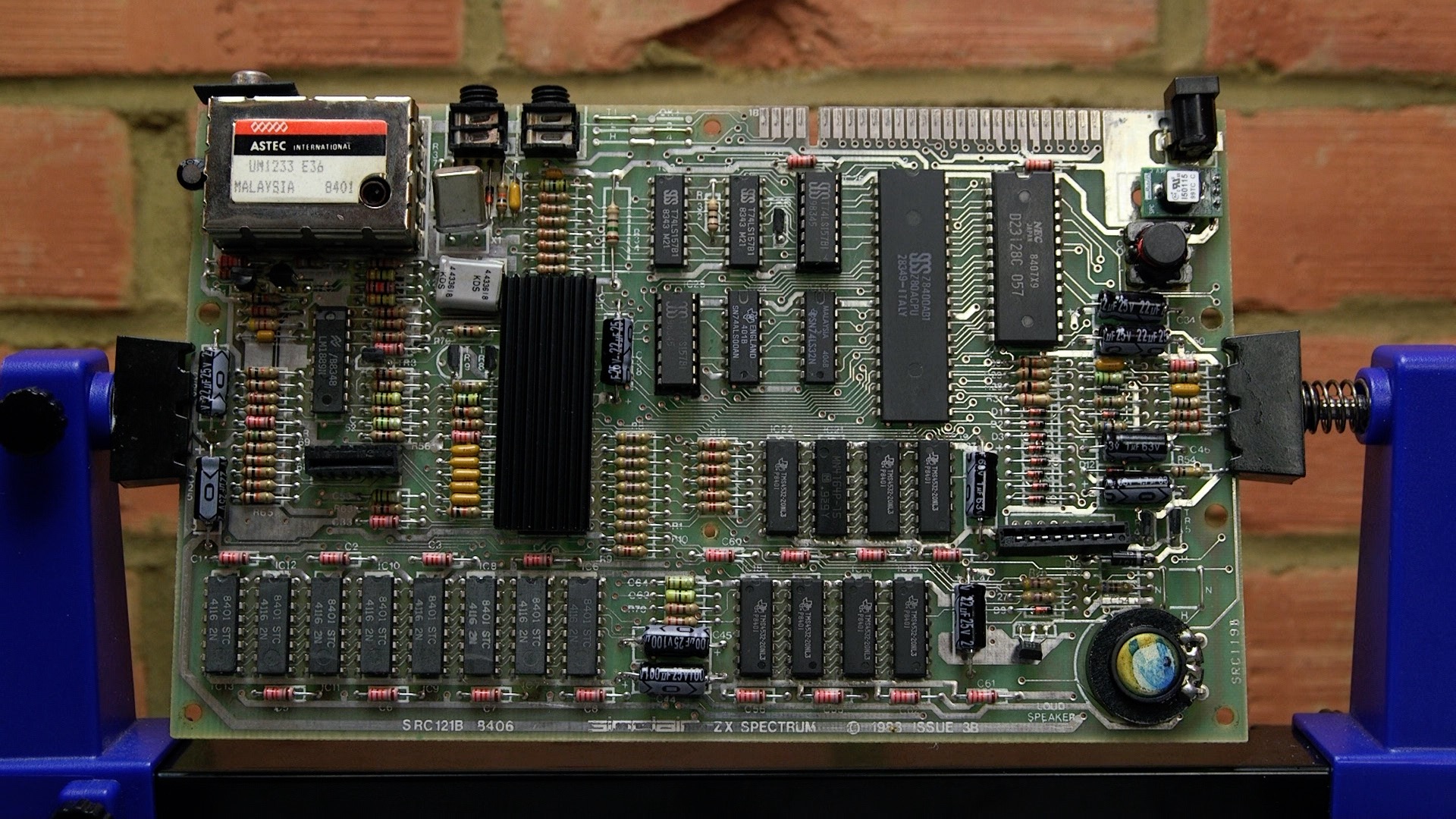
The finished board
The tape input connector prongs look a little bit bent up. This can be a problem causing issues with a tape recorder. However, having poked them down with a screwdriver they didn’t return to their original state (using the little used tape output connector as a comparison). I squirted a small amount of contact cleaner spray inside the connector and exercised it with a mono 3.5mm jack, and all appeared well.
I cleaned the edge connector with a fibreglass pencil (and hoovered up the remnants as you don’t want to inhale them). After a gentle clean with IPA and some brushes, the PCB was complete and hopefully ready for another 20 years of life:
Case Cosmetics
With the main board out of the way, time to take a look at the case.
I removed some old stickers using label remover spray. This is best left on for 5 to 10 minutes, then the label should be easy to remove.
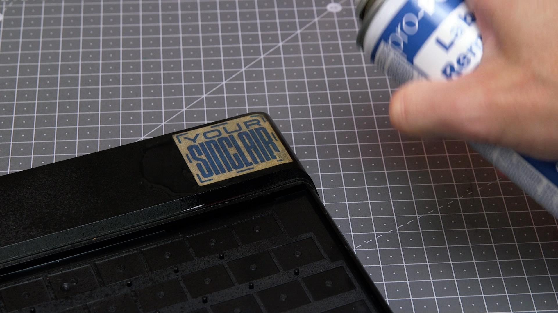
There was some old masking tape on the bottom of the unit which took a bit more persuading.
I removed the old faceplate and keyboard membrane. Take note that there are two types of faceplate. Earlier models had the metal faceplate clipped on to the inside of the case. On later models like mine, it was just stuck on.
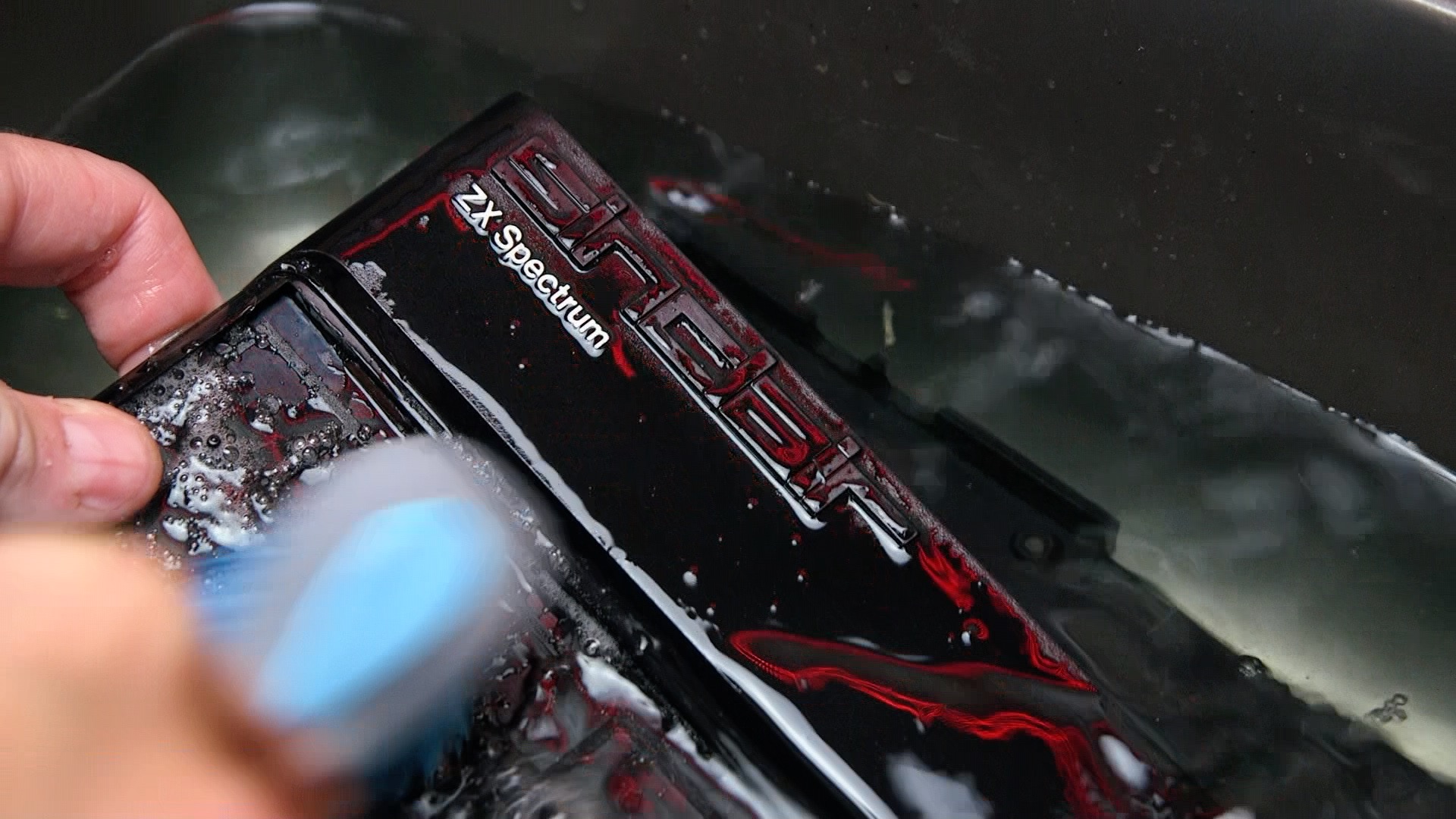
I then gavethe plastic case got a good soaking and scrub in some warm water with mild detergent (I use a small amount of Flash liquid).
I was careful to avoid scrubbing the white painted on ZX Spectrum legend. I had problems with this during my last Spectrum restoration attempt: I had tried to repaint this legend with disastrous results, so I was keeping well away from it on this occasion.
Once it was dry, I inserted a new keyboard membrane into the front panel. This was followed by a new rubber key mat, as the original had some letters rubbed off. eBay and web sellers have newly manufactured stock of these and other parts so there is no excuse for a shabby looking Spectrum.
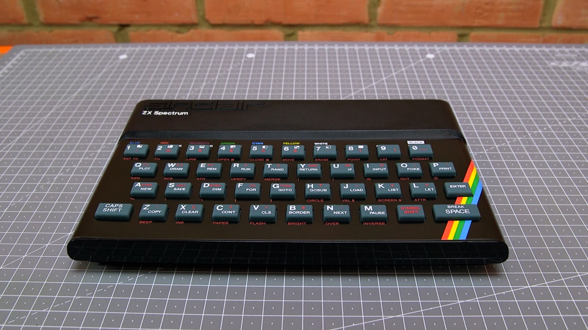
The finished result
With the machine screwed back together again, the machine looks almost as good as new. I also bought a new power supply (with the correct “centre negative” DC connector) from tfw8bit.com.
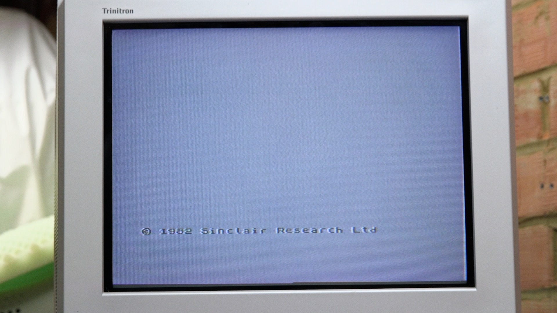
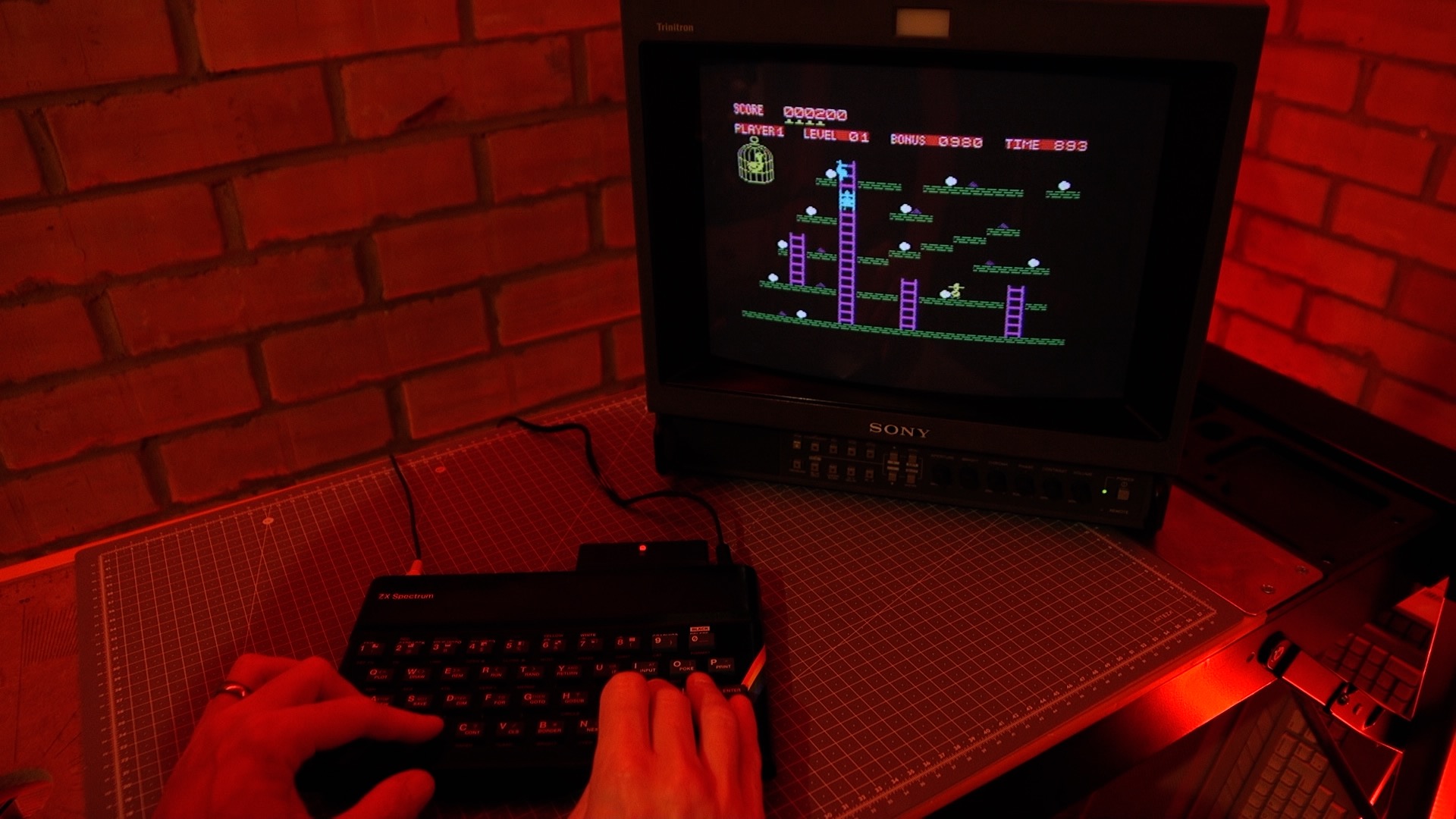
And then I put the machine through its paces, firstly with a raft of games loaded from my DivMMC Future SD card solution. This included a good few games of Chuckie Egg (good, but not as good as the BBC Micro version).
I then tried loading a few games from cassette tape, and again all was well. It does surprise me that some of these cassettes, produced as long ago as 1982, still load flawlessly. My cassette player is only 5 years old so that may well help with reliability.
I then left the machine on soak test, with the diagnostic ROM loaded and performing its tests in a loop over 24 hours.
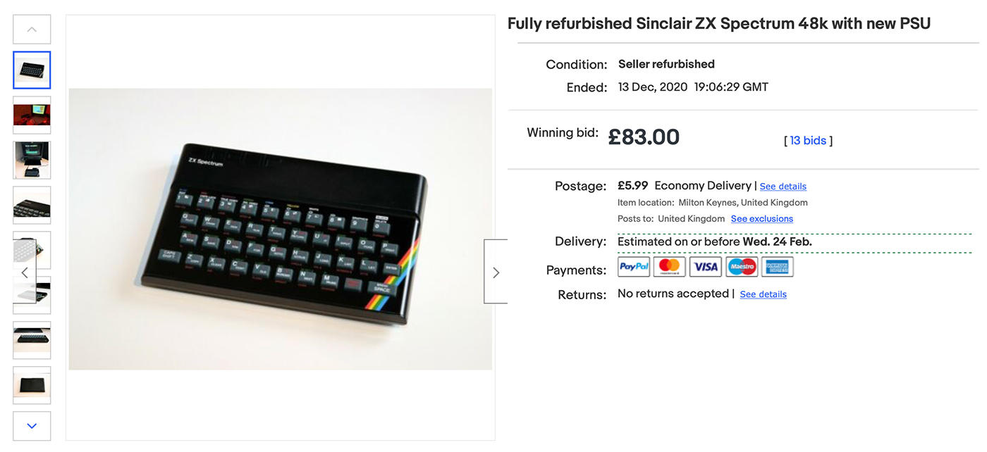
Charity Sale
I put the machine up for sale on eBay in December 2020 with the power supply, and a link to the YouTube repair video to encourage buyers. It sold for £83, and I donated the full amount to The Henry Allen Trust, a local charity.
Resources
Here are the links to suppliers for the various bits I used in this repair:
- Rubber feet (4), Dataserve Retro, £2
- Keyboard membrane, Retroleum, £8.75
- Rubber keyboard mat, Retroleum, £12.99
- Metal faceplate, Retroleum, £17.99
- PSU, tfw8bit, £20.98 inc P&P
- Capacitors, Retroleum, £2.99
- DC-DC convertor, Retroleum, £4.99
- RAM IC, Retroleum, £1.50
Total cost (approx, as P&P was extra): £72.19
Clearly if you were doing this for financial gain, you’d be mad. The eBay and PayPal fees would wipe out any profit. However, this was for fun and for the benefit of charity.
This is why decent “refurbished” machines are either fixed price “buy it now” of at least £100, or lower cost with just the capacitors replaced and a bit of spit and polish on the front panel.
Conclusion
I really enjoyed working on my 3rd Spectrum 48k repair, and was actually pleased to find an electronic fault so that it could be fixed, although it was rather trivial with the benefit of the diagnostic ROM.