Introduction
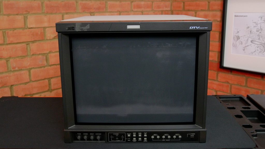
In this video I take a look at a JVC DT-V1710CG video monitor which I bought for use with my retro computer collection. This was one of the last broadcast standard CRT monitors produced, and I had high hopes for the picture quality. However, it arrived in a scruffy condition with scratches on the screen and damage to the anti-reflective coating.
In this project, I tear down the monitor, repair the damage to the screen and give it a check over – the electronics and the tube condition are both assessed. I then connect it to some of my collection of retro computers (Amiga A500, BBC Model B, Atari ST) using RGB and review the picture quality. I also attempt to connect my Spectrum 48k using composite video.
In the second part of the video, I try out some replacement film to try and improve the contrast.
History
This model was possibly the last in the line of high spec. monitors made by JVC for use in broadcast television, for example in TV galleries and editing suites. My monitor was manufactured in 2008. I have found evidence from UK resellers that this monitor was last available for sale in 2010.
Sony stopped selling their popular and highly regarded PVM line in around 2005 although the more expensive BVM line was available for about 5 years after this. Sony began to push their LCD range of monitors instead. Also European legislation effectively phased out CRT’s due to harmful elements being used in their construction. This JVC monitor appears to have filled the gap left by PVM’s and found its way into many facilities, often in “quality monitoring” positions. The fact that it could be used with HD video made it a good choice in many installations. I bought one of these monitors new around 2007/8 when I worked at BBC London. This was bought as a spare to use in graphics preparation or camera racking positions if their monitors failed. In fact they had failed, and this had left us without a suitable spare whilst they were repaired on previous occasions. When the station moved to Broadcasting House, this JVC monitor became the graphics operator’s primary check monitor, where it was used with the Quantel Paintbox. I liked this monitor’s size and picture. You may wonder why we didn’t opt for Sony BVM monitors – after all the “B” stands for “broadcast”. The answer is that these monitors were many times more expensive – £10,000 to £20,000 and they were simply beyond our budget.
This JVC model originally sold for around £1400 excluding VAT, without any input cards, in 2008. I paid £200 including all fees for my monitor from a broadcast auction site in 2019. A partially removed label shows this had been previously owned by xxx who are a big rental company near London.
Video inputs and connecting to my retro computer collection
Input cards can be placed in any of the three slots in the rear of the monitor, and different cards were available for the following video formats:
- HD-SDI (broadcast standard digital video, HD)
- SDI (broadcast standard digital video, SD)
- Component (Y,Pb,Pr) and RGB, with composite or H and V syncs
- Composite / S-Video
My monitor came with both an HD-SDI and SD-SDI card fitted.
Retro computers have the following video outputs, and these are ranked in order of picture quality, worst first:
- RF – TV antenna type signal
- Composite video – a single wire carries the colour, black and white and sync signal
- RGB – separate connectors for red, green and blue video signals. The sync may be carried on the green wire, or on a composite (H&V) sync connector. PC’s use separate H and V sync signals (e.g. as found on the common 15HD connector used for VGA type signals) with their RGB output.
- Component – Y, Pb, Pr – very similar to RGB (and identical quality), but the colours are “matrixed” to Y (luminance, or black and white), Pr (Partial red, R-Y) and Pb (Partial blue, B-Y)) – I don’t have any machines that use this format, but I believe some consoles use it. Also my Samsung DVD player that I used in this video has this type of output.
I therefore had to purchase an additional card to connect my computers, most of which have RGB outputs. The original JVC RGB/Component card, model IF-C01COMG commands high prices on eBay. However, there are in fact very few components on the board, and some enterprising folks have reverse engineered it and sell the cloned boards on eBay. I bought a card from Linuxbot3000 for about £80 (including import duty). This card has BNC’s for RGB or YPbPr and connectors for horizontal and vertical sync (or composite sync may be input on the first of these).
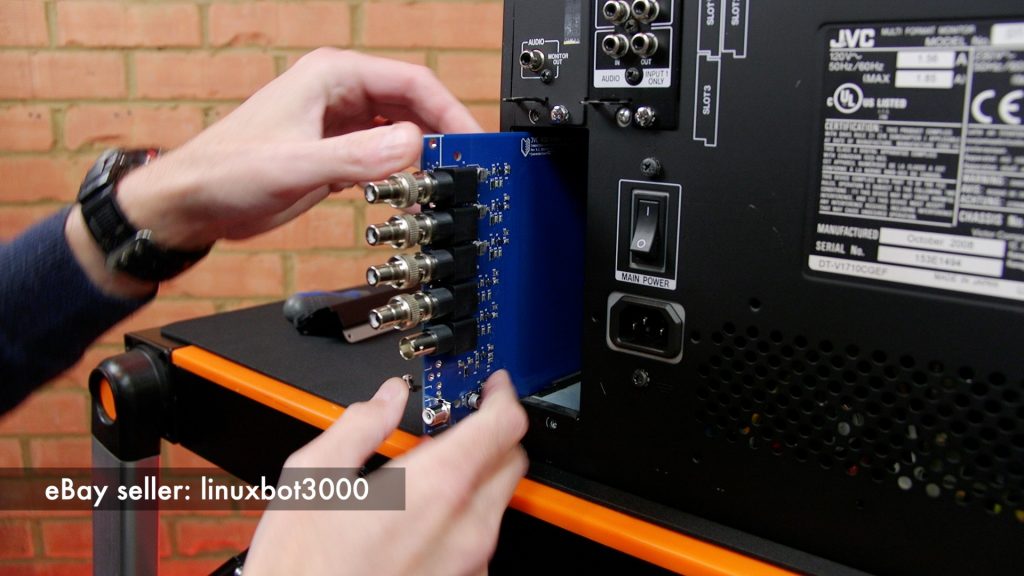
In order to use this card, you press one of the input buttons on the front panel. There are 3 slots each of which has two inputs. My card is present in slot 3, and this card uses input E for component, and input F for RGB. Additionally, if sync is present on the H (or H and V) sync connectors (rather than being combined with the green signal) , you need to go into the SETUP MENU and change the sync from INT (internal) to EXT (external). To enter this menu you need to press the VOL – and DOWN buttons together. My computers output a composite sync signal (H and V sync combined) and this is connected to the H Sync connector on the monitor.
My Spectrum 48k models have only a composite video output. The instruction manual for this monitor shows a composite video interface (IF-C01PNG) – but I have never seen one for sale. In fact I remember trying to get one in 2008 and was told by JVC that it had been discontinued. I have never seen this card for sale 2nd hand. Some other means of connecting the Spectrum is required, and I discuss this later on.
Specifications
The brochure for this monitor shows the following specs:
- Flat, AG display – This is completely flat and square. AG means aperture grill. This is Sony Trinitron-type technology which has vertical stripes of phosphors, rather than a pattern of dots and a shadow mask. This means that the display is brighter, and has a higher vertical resolution.
- 4:3 or 16:9 aspect – The tube is a 4:3 aspect ratio. However, the monitor would have shipped with a clip-on plastic bezel that masked off part of the screen leaving a 16:9 portion exposed. The user would use the 16:9 button on the monitor to “drop the scans” so that the monitor only scanned this portion of the screen. There were very few 16:9 widescreen professional tubes produced as it was uneconomic to do so.
- Metal case – Professional monitors are well shielded and can be placed close to other monitors without interference.
- 3 slots for video interfaces – 2 inputs on each slot (6 inputs)
- 17 inch diagonal screen size (a 19 inch model was also available)
- Degaussing coil – When the monitor turns on it briefly powers up a coil wrapped around the tube. This should dissipate any residual magnetism that may affect the colour purity. Care needs to be taken not to place bank cards or floppy disks near the unit.
- Wide range of video formats supported – 480i, 576i, 480p, 576p, 720p, 1080i, 1080/24psF
- 800 TV lines of resolution – This is the so-called horizontal resolution of the display. This is worth taking a moment to discuss, as this is not well understood (as can be seen from various internet forums).
Display Resolution
The vertical resolution is fixed by the number of lines present in the TV signal (625 lines in the UK standard definition signal), although not all contain picture information. The vertical resolution can be affected by the vertical scan size (which is adjustable). Any of the 625 lines in the UK standard definition TV standard, that are scanned on the tube face will create a visible line.
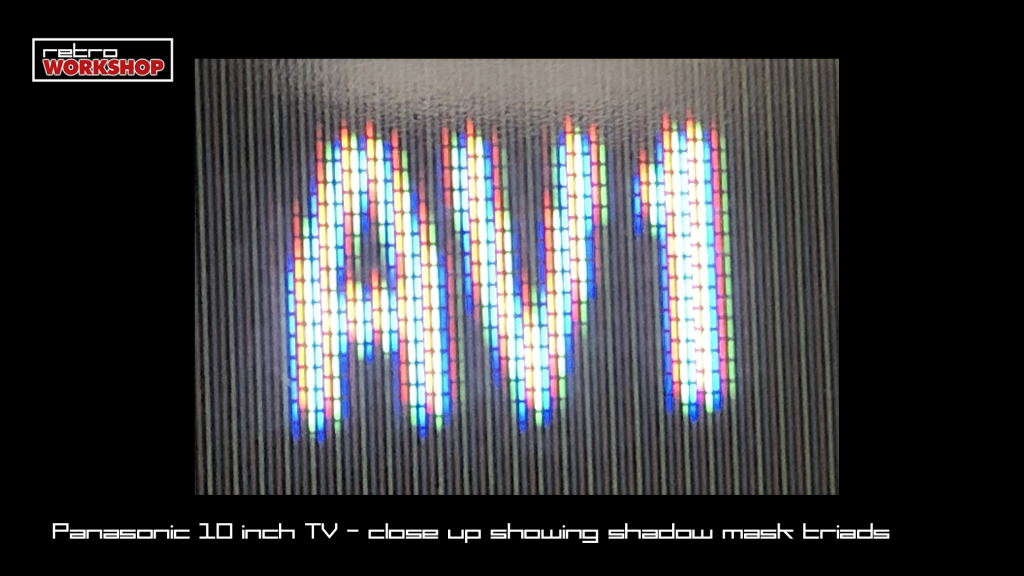
On the more common shadow mask display, there are clearly defined spots of colour – these are called triads and these are small rectangles of red, green and blue phosphor. These may be thought of as pixels as they are defined picture elements. However, there is no mapping between a line of the video signal and any given line on the display. You could adjust the vertical size or position so that a line in the video signal hit any given line on the phosphor display. Additionally, a shadow mask monitor may not have 625 vertical triads. However, successive lines in the video signal may illuminate the same physical line of dots on the display, so although the information is not lost the display resolution is limited. For example, I have small Panasonic CRT TV. This 10inch diagonal TV has a screen height of about 14.5cm. I have measured 15 vertical triads in 7.15mm. I calculate there are approximately 315 vertical triads. You can see that the vertical resolution is less than 625 lines that we know the broadcast signal comprises. Horizontally adjacent triads are also offset by 1/2 a triad which is a sort of compromise.
Horizontal resolution was a common figure quoted for professional monitors in the days of the CRT display. An analogue signal does not have defined pixels, but a comprises a waveform that varies with picture brightness. However, a monitor does have a fixed pattern of coloured dots or stripes, which limit the resolution. It is the combination of the signal (bandwidth) and pattern on the tube face that limit the horizontal resolution.
Horizontal resolution is a means of measuring the number of vertical lines that could be displayed on the screen and still be discernible. For example, if you input a signal which had 400 white and 400 black vertical lines, interleaved one after the other, you would be able to discern all the lines on this display which can resolve 800 TV lines. This is beyond the resolution of a digital SD signal (720 lines in 625 regions) but far less than the 1920 lines on a 1080i system. A high bandwidth analogue RGB signal could deliver this resolution, as it is not limited by pixel boundaries.

People often get confused with this metric, and get caught up with modern comparisons with PC resolutions which have more clearly defined horizontal resolution (eg 640×480 has 640 horizontal pixels). Combined with a digital connection to a modern LCD display which as defined pixels, a pixel in the computer’s frame buffer may be directly displayed on the monitor (if the same resolution).
The CRT monitor’s beam is analogue – it sweeps left to right and the intensity varies. There are no pixels in the beam. The surface of the tube does contain red, green and blue phoshor stripes (in the case of this AG display). Therefore the resolution is limited by the number of vertical stripes (which could be counted if you were very keen). The pitch of the stripes is shown in the spec as 0.25mm.
The bandwidth of the display electronics also affects the resolution. The higher the bandwidth, the higher the resolution. So the monitor’s horizontal resolution is affected by the electronics bandwidth and the pitch of the phosphors on the display, in the case of an analogue input signal. In the case of a digital input signal (e.g. SDI) which does contain pixel information, the resolution is limited by the input resolution, the bandwidth of the electronics in the monitor, and the pitch of the phosphors on the display.
In summary: modern LCD displays fed with a digital connection, map an incoming pixel to a defined pixel on the screen. If there isn’t a 1-to-1 mapping (for example you are displaying 640×480 on a 1600×1200 LCD) the monitor needs to do some maths to work out how to map the pixels to the display. This usually involves loss in quality. A CRT is a different beast entirely. You can think of the cathode(s) emitting a beam of light (actually electrons) and this beam is scanned across the tube face left to right, one line at a time, and illuminate any phosphor in its path. If we move the beam slightly as we can do with tweaks to the electronics, we just illuminate a different phosphor. Think of a theatre “follow spot” operator swinging the light around a room.
Monitor check over
The monitor arrived in a scruffy condition It was certainly not the monitor shown in the photos on the auction site. There are scratches to the metal case, the front bezel, and it was missing the widescreen bezel. Most worrying were the scratches on the surface of the screen.
I powered up the monitor and fed in various test patterns using a DVD I made up. I created these patterns in Photoshop, FCP X and created the DVD using DVD Studio Pro. I am pretty confident the aspect ratio is correct.
Retro computer users can make use of a free set of test patterns called the “240p test suite”. Disc images are available for many consoles, but I don’t own any of these. However, I did download the “grid” pattern and burn it to the disk.
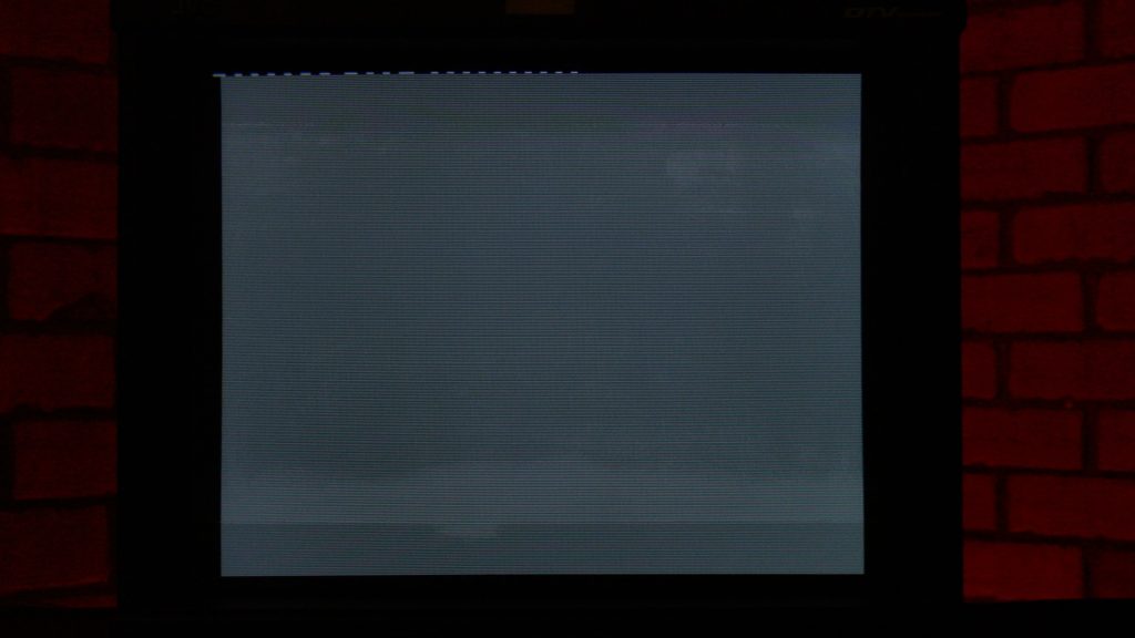
The grey field (grey image) should be uniform throughout the picture. However, it clearly wasn’t as there was damage to the antireflective coating on the screen. This coating can be removed with acetone (e.g. as found in nail polish remover). Screen burn would also show up on the grey field. Luckily there is no screen burn on my monitor. This can be an issue with CRT’s, particularly those used in edit suites where timecode displays were often left on screen and easily burned into the display.
Individual fields showing a full image of red, green and blue demonstrated that the colour purity was correct. With a red image, only the red gun should fire and illuminate only red phosphors on the screen. Had I been able to see and spots of green or blue, this would suggest a colour purity error.
The convergence pattern (or grid as it is also known) is usually made of lots of white squares, and a big circle. The small squares allow you to check the geometry. The squares should all be “square” (geometry) and evenly sized across the screen (linearity). The large circle should of course be “circular” and not an oval. An error here would indicate the H and V size was incorrectly set and your would have an aspect ratio error.
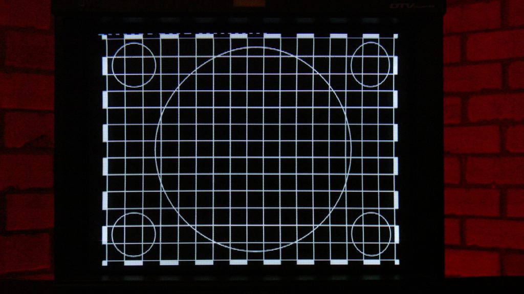
The fine lines of the convergence pattern should all be white. If they have coloured edges, this suggests that the “convergence” of the red, green and blue beams is incorrect.
Some grid patterns (e.g. that on the “240p test suite” grid) has some white dots around the edge. These dots show the 5% border of the active video area, and should be in the middle of the last square in the active picture. Domestic televisions are set to “overscan” the image – that is to say that the image is cropped. You usually lose about 10% on a TV, but this was never set accurately at the factory and could also drift as the set aged. This monitor (as per the spec) is set to crop or overscan 5% when in the “normal” mode. Therefore the dots on this pattern should appear at the edge of the image, which they do. This suggests H and V size is set correctly. This 5% overscan is not standardised – for example some PVM’s show 7% overscan on their spec sheets.

Pressing the “underscan” button the monitor shows the entire image, with a small border. The allows technicians to check there is nothing untoward in the shot (e.g. a microphone boom). And no flickery, horrible signals in the active picture area (don’t get me started on that one).
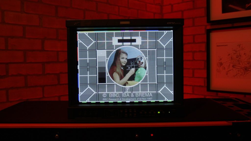
The BBC Test Card F combines features of many test patterns into one image:
- squares for linearity
- large circle for aspect ratio
- girl, doll and blackboard – a real scene should look ‘normal’ and we can assess skin tones – the eye is very sensitive to errors in skin tone
- grey squares should be grey – check of colour balance of the TV
There are many more features of the BBC Test card, and there is a discussion of these here:
My monitor looked to be in excellent alignment. However the scratches on the screen and damaged anti-reflective coating spoil the picture to some extent.
There is an hours meter on this monitor, in the SETUP MENU. This monitor has done 7000 hours which is less than a year of constant use. I reckon a broadcast monitor should give at least 5 years or more of constant use, dependant on the environment (air flow). For example I’ve know PVM’s run 24/7 to go for 7 years before they need maintenance. However, image burn can be an issue with monitors that have been in constant use. Even without burning in logos, normal scenes can cause burn and this results in a slightly “muddy” looking image.
Tear Down
I’d been giving some thought to a serious attack on the screen with a polishing disk and some polishing compound. This may well have gone wrong, but I was up for the challenge. He who dares, wins (sometimes!).
However, I’d been looking around the ‘Retro Man Cave’ Discord server and speaking to folks in the #CRT room. A user suggested this monitor had a plastic film on the screen, and this was removable if the screen was disassembled. I had not heard of films on professional monitors, but sure enough some Googling revealed this was indeed a thing, so I decided to give this a go.
I took the monitor apart observing the following precautions:
- Discharge the tube’s primary anode, by shorting out the EHT cap to the outside of the tube (ground wire). This can retain charge of up to 25,000V even when the set it depowered. You hear a crack if there has been a discharge. On some modern designs it will discharge by itself some time after being depowered. Additionally, if the EHT lead is left disconnected, it can charge back up on its own (e.g. overnight) so you should discharge it periodically (every day) if left unplugged at the EHT anode connector on the tube.
- Cathode Ray Tubes (CRTs) are vacuum tubes – all the air has been pumped out. If you drop or break the tube it can implode, which means glass gets thrown everywhere at high speed. It is best practise to wear goggles and a facemask when handling tubes (but they are OK in their chassis where they are protected by the case on most sides). Watch this video and be cautious: IMPLOSION! 40 inch tube TV. If you knock the thin glass at the tube neck, you are unlikely to have an implosion. However, a crack can cause air to rush in and the tube is rendered useless.
- High voltage capacitors in the power supply circuit (e.g. 400V caps) may retain charge after the unit has been unplugged. Check the voltage with a multimeter (DC range) and short out the cap with some wire if required to discharge it.
- If you need to work on the monitor when it is powered up (to check signals etc.) you should plug the monitor into a (tested and known good) RCD. If you come into contact with anything live, the trip should activate and cut the power. Some old TV’s and monitors (I think we’re talking pre-1990 here) have live chassis – the metalwork in the chassis is at mains potential, so take extra care. In this case, it is advised to use a safety isolating transformer.
- You should not attempt any work on mains powered equipment without experience. This is of course stating the obvious, but without basic knowledge of components, safety connections and hazards, you put yourself at risk and anyone that may use the equipment after you. Nuff said.
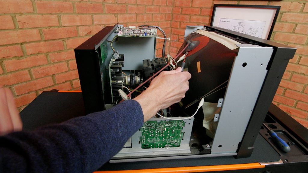
The monitor was quite clean inside with just a small amount of dust. It was straightforward to take apart, and I just noted down the paths of the connecting cables so I could put them back afterwards.
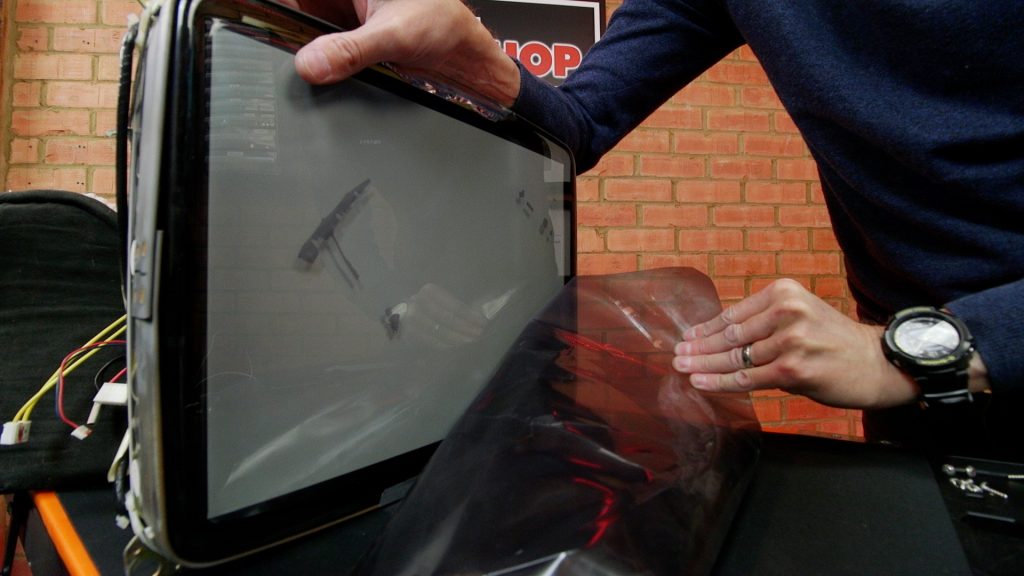
I propped the tube up on a soft dog bed as I didn’t want to damage any of the delicate coils or magnets on the rear of the tube. It was a simple matter of peeling of the film from the tube face, although it was very sticky and quite thick film.
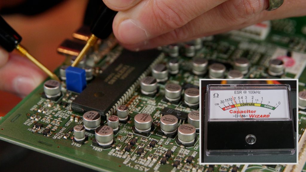
Capacitor check
Retro computer folks are somewhat obsessed with replacing electrolytic capacitors in everything they touch. However, I do not subscribe to this approach. I would rather test their health with my ESR meter, and change only where necessary. The exception here is something like an Amiga 1200 (or other early 90’s micro) whose early SMT electrolytics are renowned for leaking, so a pre-emptive swap would be good practise in this case.
This monitor isn’t particularly ancient (built in 2008) and most capacitors are full size radial electrolytics. You can see from the brandson the caps that JVC has used good quality caps throughout.
If you replace capacitors on a CRT monitor you have to be especially careful, particularly in the scan circuits, to use capacitors suitable for the high ripple currents and frequencies present. Any old CPC capacitor will probably NOT be as good as the original. You can see lots of brands and series used in this monitor so they have been very carefully selected for use by the designer.
I found all the capacitors on the main board to be in good condition. There is a small SIGNAL board at the top of the monitor, which deals with the incoming video signals, and also houses the microcontroller. The small 1 and 3.3uF SMT caps on this board were a bit marginal. They were “compare” on my meter. I do not have any of this type to compare with. I will order some up and replace these at a later date.
Most importantly I suspected the main board caps were good, as ageing caps affect the picture geometry and we know this to be good from the earlier checks with test patterns. OK, I concede that issues with ageing caps could to some extent have been tweeked away in the monitor settings by its previous owner, but we now know the caps are good, and the geometry is good. We have some quantitive knowledge about the health of the monitor. No need to replace those caps on spec!
The avid reader may have seen in an earlier repair of a Spectrum 48k Plus computer, that some caps that measured OK on the ESR meter were replaced anyway, and this led to an improvement in picture quality. This is indeed worth remembering. However, on this occasion, there was no issue with image quality. OK I know I’m going on about this too much now…
Clean Up
The usual remnants of sticky labels were removed with a cloth and some IPA. There were two tougher remnants on the top of the case. I used some CPC “label remover” spray which works well if left on for a few minutes and then carefully rubbed.
I have the case a good wipe over with some mild kitchen detergent spray.
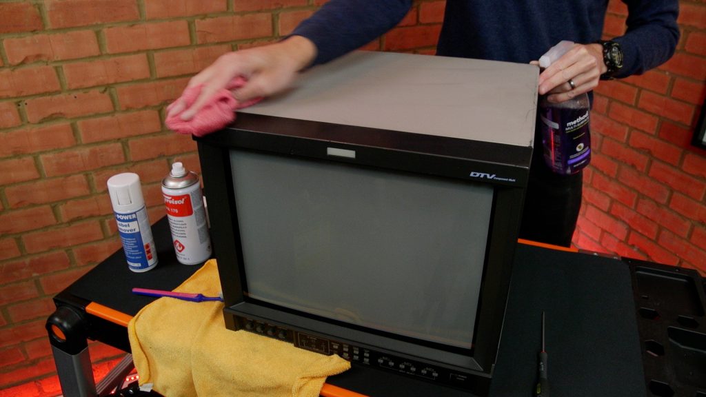
In an ideal world I would get the grey metal case resprayed. However, we are in The Corona lockdown at present which makes this difficult. Also the scratch on the front plastic bezel is less easy to fix. We do have one of these monitors at work which has failed. I suspect the tube on that unit (it had been left powered up for 12 years). I will probably ask the boss if I can have the monitor and swap the case and bezel.
Testing
After a quick check with my test pattern DVD I can see that the blotches on the grey fields are now clear.
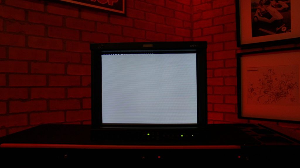
However, without the filter in place the tube face looks mid-grey rather that the dark grey of previous with the power turned off. The filter was acting as a neutral density as well as having anti-reflective properties.

This effect is noticeable with the monitor powered and in use. The strong lights in my workshop certainly didn’t make the image look good on the monitor. However, in more subdued lighting conditions the picture does look very good indeed.
See later on for a proposal to add a new screen filter.
I connected some of my collection of retro computers using RGB to the monitor.
Amiga
All the games I tested generate a progressive scan display. Although the UK TV system has 625 lines made up of two “interlaced” fields, many older computers create a slightly non-standard display signal to simplify the computer electronics, and reduce flicker caused by small details in text and fine lines.
Using my Tektronix waveform monitor, and an oscilloscope, I can see the Amiga outputs a video signal with 50 frames per second each with 312 lines. The effect of this is that adjacent scanlines are further apart than when using interlaced video. This can accentuate the scanlines, as the active lines have effectively black lines in between them. The distinct scan lines are a much-loved feature of CRT displays when used with computers from the 1980’s and 90’s.
Another bug bear: Internet folks describing the “scanlines” as the lines in between the lines that are actively scanned. No they are not. Scanlines are the lines that are actively scanned. Additionally it is said that you need a progressive type scan to see the scanlines. This is not the case. Using interlaced video the scanlines are also discernible, as I can see on my test DVD (625i) and the BBC Micro (see later).
The monitor’s on-screen display shows the video format as 576/50i (what I’d call 625i/25) as it is a very close match and the monitor is quite happy with this signal, just like our TV’s back in the 80’s.
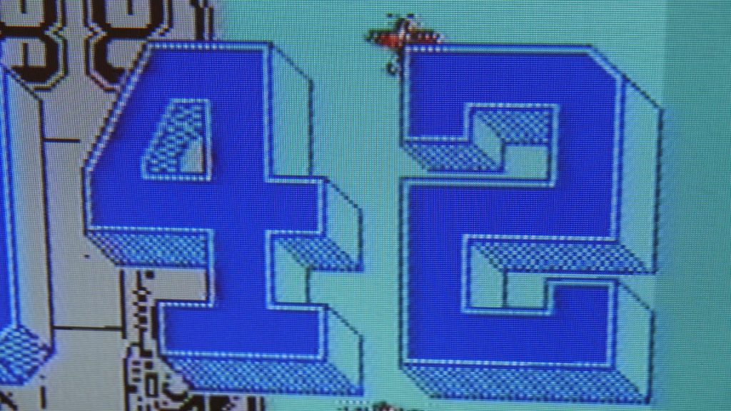
The first game I loaded was R-Type which I know has great graphics on many systems and is a game I remember from back in the day. There was an R-Type arcade cabinet in the town where I grew up. It is quite a difficult game but I enjoy playing it. This game looks quite amazing on this monitor. A big advantage of the Amiga over other systems is that it doesn’t have a border – the picture extends to the edge of the screen.
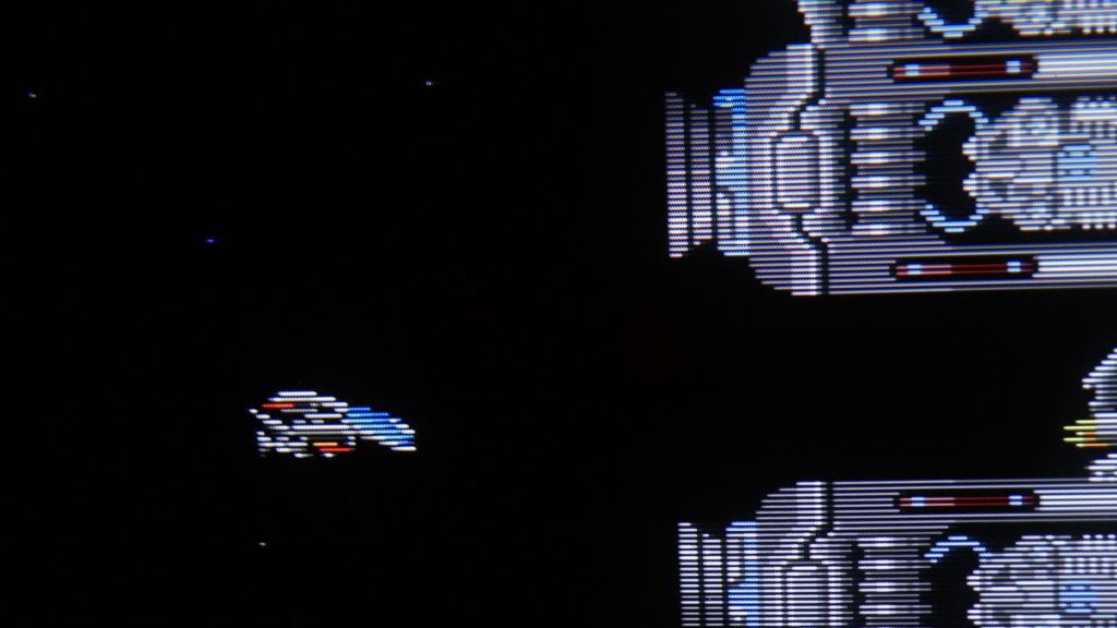
Verdict: 10/10 Amazing picture. Detailed graphics, punchy scanlines and deep colours
Atari ST
Unlike the Amiga, the ST has a thick border around the picture. You can adjust the H and V size on this monitor to get rid of the border. In the SETUP MENU you only get limited control, and can’t eliminate it.
If you go into the SERVICE MENU you get more control and can almost eliminate the border. To get into this menu press:
- [down] + [MENU] then quickly press
- [down] + [Volume -] then quickly press
- [Volume +]
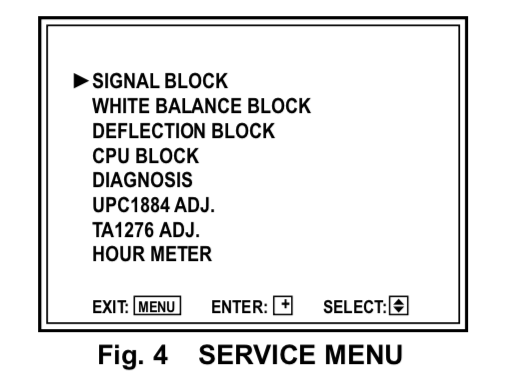
You can then get into the DEFLECTION BLOCK menu. You get a set of tweaks for each type of input card, and input standard. You get separate tweaks for UNDERSCAN and NORMAL (overscan) so you could set up two banks of settings for each video standard if required.
So for my RGB card I had to use the DG menu (labelled 576/50i). You can simply adjust values for H and V size, although you only get the parameter number (e.g. DG01) and need to refer to the service manual for the description of each parameter:
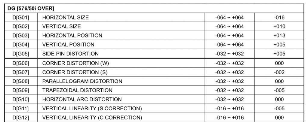
Once I’d tweaked the values, I played a couple of games including Super Hang-On.
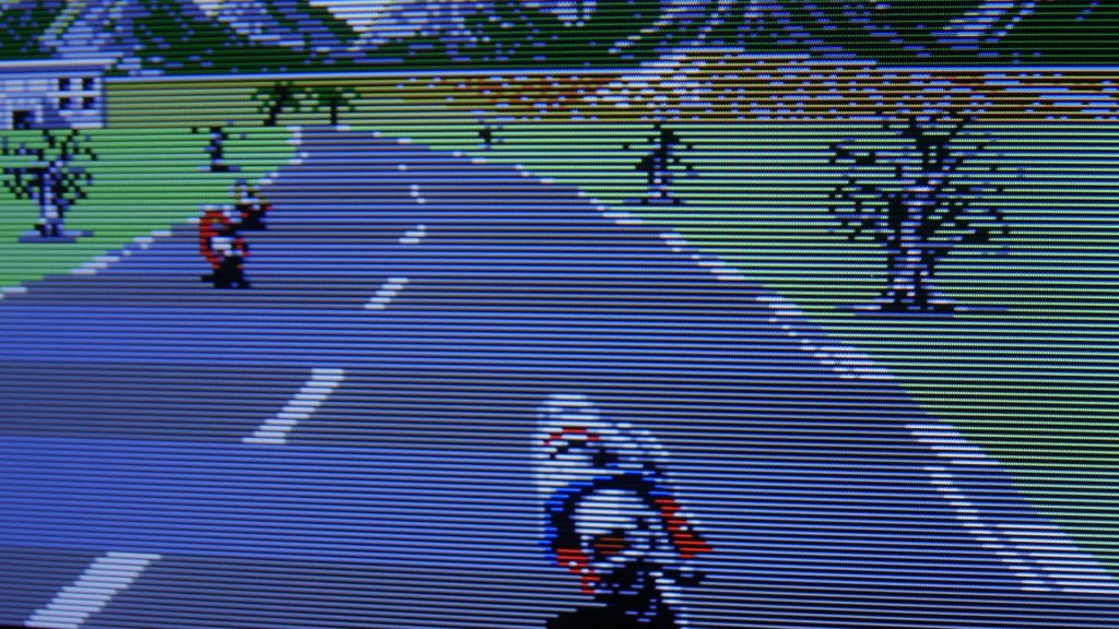
Graphics were very crisp and punchy. Like the Amiga, games use the fudged 312 line / 50 fps progressive video format.
If you have lots of white on screen, the image can be slightly jittery (side to side), for example when booting into the GEM desktop. This seems to be worse depending on the resolution. I have two Atari ST computers and one was worse that the other. I haven’t done any work on these machines and it may be the computers themselves need some work, for example to the power supply.
Verdict: 8/10 More to do with graphics not being on par with the Amiga than the monitor
BBC Micro
This uses a standard interlaced video output for most games. The image does have a bit of flicker discernible for this reason. This really isn’t something you would have noticed years ago, as we got used to the look of CRT displays. Nowadays, we’re used to LCD screens with no flicker, even though we still use interlace for many HD TV broadcasts.
I do know that different monitors can make interlace flicker look worse, so maybe this is one of them. I’ve got a feeling that Aperture Grill / Trinitrons are worse in this respect, from memory. This does seem worse than I remember from a CUB monitor, but I don’t have one here to compare side by side.

However, flicker aside, once I loaded up Chuckie Egg and started playing I didn’t notice it. The image is bright and punchy and the game never looked so good. You just don’t get the depth of colour on an LCD. There is something too, about being behind glass that helps. It’s shiny rather than the dull matt of many LCD monitors (something I never liked about LCD’s) with great contrast. There is a reason Apple put their LCD’s behind glass on the iMac and MacBook Pro.
Verdict: 8/10 Superb picture but some flicker on the interlaced image
Spectrum 48k
This computer only has a composite video output. I don’t have the composite interface card for this monitor (and I’ve never seen one – I think they were discontinued fairly early on). But I do have a Extron video scaler. This can accept a PC input, composite video, S-Video, RGB or component video and scale it to a particular resolution up to 1080×1920 (HD). It has an analogue PC type output with a 15HD connector. Using a 15HD to 5x BNC cable I was able to connect the scalar to the JVC monitor.
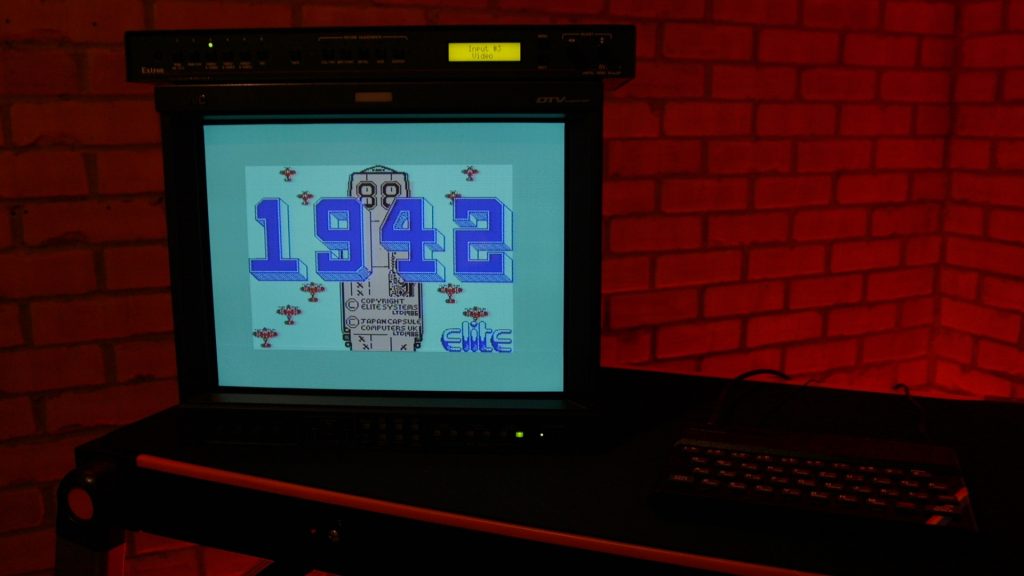
The monitor can handle a couple of PC resolutions eg 640*480 and 800*600. It can also handle other “progressive” scan resolutions such as 720p and what the on-screen display shows as 480/60p and 576/50p. These are line doubled 525 and 625 line signals (showing only the active lines therefore 480 or 576). The scalar can produce these formats so I set it to 576/50p and was able to use the Spectrum.
The Spectrum also produces a pseudo-PAL output – it is actually 312 lines at 50 frames per second, like I saw on the Amiga and ST games tested earlier. The scalar seems quite happy with this signal (unlike some other equipment I have such as a Vistek PAL to SDI convertor, and a timebase corrector).
The monitor (and possibly scaler combination) shows up the defects of the decoded PAL signal – at transitions between strong colours you see shimmering. The Spectrum also makes PAL look worse as there is a moving pattern at coloured edges. This is because the computer’s video generator is not locked to the PAL colour subcarrier frequency. UPDATE MAY 2021: I have since used this Spectrum on my Sony 14 inch TV and you still have these issues at the edges of colours, so the scaler is doing a good job; it is the design of the Spectrum’s video output that is the limiting factor here.
Verdict: 5/10 Shows up limitations of the composite signal. But better than nothing! You may be better with a 14 inch shadow mask type TV with a SCART input. Or use one of the later Spectrum models which have RGB video outputs.
240p and all that jazz
There is lots of talk and excitement about “240p” signals from retro computers and consoles on the internet. These non-standard video signals can be challenging to display correctly on modern devices.
I’ve written a page trying to decypher and explain what this is all about….
Replacement film (video – part 2)
Once I put the video out, a couple of viewers suggested that I investigate some replacement film. They suggested anti-reflective film – but I don’t think that is what is required. Undoubtably the original had anti-reflective properties, but reflections are not what is disconcerting when the film is removed. The problem is contrast: The tube face is grey and was made darker by a dark film. Without the film the tube face is a mid grey. Therefore it cannot show black correctly. The original film has what photographers and lighting people would call an ND or neutral density effect.
I was shopping at Sainsbury’s supermarket, and had some inspiration in the car park when I saw a car with tinted windows, or privacy glass as it is known. This got me thinking about suppliers of car privacy film that can be fitted to glass. Also film suitable for buildings to cut down on the light coming into the home.
I purchased two types of film to try out:
- Car window film, 50 % strength, from Window-tint.co.uk approx £6 + postage
- Purlfrost NEU-50 approx £20 + postage
The Purlfrost was a superior product: better instructions and it didn’t get wrinkled when applying, unlike the window-tint product. However, the car film produced a darker result and I decided I could live with a little blemish. This was the film I chose to apply to the screen.
Summary
Once I got over the less than perfect cosmetic condition and removed the damaged screen filter I have been very impressed with this monitor. I have compared this monitor to my 14 inch Sony PVM 14M2E, my domestic Sony 14 inch TV and the JVC is clearly the winner in terms of image quality. It is a large and heavy box (I think it is more than 22Kg), but it is now my daily use CRT monitor. It does lack a composite input which is very useful for some computers and consoles.
If you are in the market for a nice CRT I would definitely recommend this. However, you need to check it out in person:
- Check the hours meter – it shouldn’t have done 50,000 hours!
- Check it with real pictures – check for image burn.
- Check the screen for damage. Take your time as this may not be immediately obvious.
- You’ll need an RGB card. The chap on eBay doesn’t sell them all the time, so either get it in advance or expect a delay. And don’t be surprised when the package needs the customs bill paying at the Post Office (about £24 from memory).